ÅÅÅ
ÅÅÅ
ÅÅÅ
ÅÅÅ
ÅÅÅ
ÅÅÅ
ÅÅÅ
ÅÅÅ
ÅÅÅ
500 1000 1500 2000 2500 3000 3500 4000 4500 5000
5
°
10°
15°
20°
25°
30°
35°
–5°
0°
–10°
–15°
0
ÇÇÇÇÇÇÇÇÇÇÇÇÇÇÇÇ
ÇÇÇÇÇÇÇÇÇÇÇÇÇÇÇÇ
ÇÇÇÇÇÇÇÇÇÇÇÇÇÇÇÇ
ÇÇÇÇÇÇÇÇÇÇÇÇÇÇÇÇ
ÇÇÇÇÇÇÇÇÇÇÇÇÇÇÇÇ
ÇÇÇÇÇÇÇÇÇÇÇÇÇÇÇÇ
ÇÇÇÇÇÇÇÇÇÇÇÇÇÇÇÇ
ÇÇÇÇÇÇÇÇÇÇÇÇÇÇÇÇ
ÇÇÇÇÇÇÇÇÇÇÇÇÇÇÇÇ
ÇÇÇÇÇÇÇÇÇÇÇÇÇÇÇÇ
ÇÇÇÇÇÇÇÇÇÇÇÇÇÇÇÇ
ÇÇÇÇÇÇÇÇÇÇÇÇÇÇÇÇ
ÇÇÇÇÇÇÇÇÇÇÇÇÇÇÇÇ
ÂÂÂÂÂÂÂÂÂÂÂÂÂÂÂÂ
ÂÂÂÂÂÂÂÂÂÂÂÂÂÂÂÂ
ÂÂÂÂÂÂÂÂÂÂÂÂÂÂÂÂ
ÂÂÂÂÂÂÂÂÂÂÂÂÂÂÂÂ
ÂÂÂÂÂÂÂÂÂÂÂÂÂÂÂÂ
ÂÂÂÂÂÂÂÂÂÂÂÂÂÂÂÂ
ÂÂÂÂÂÂÂÂÂÂÂÂÂÂÂÂ
ÂÂÂÂÂÂÂÂÂÂÂÂÂÂÂÂ
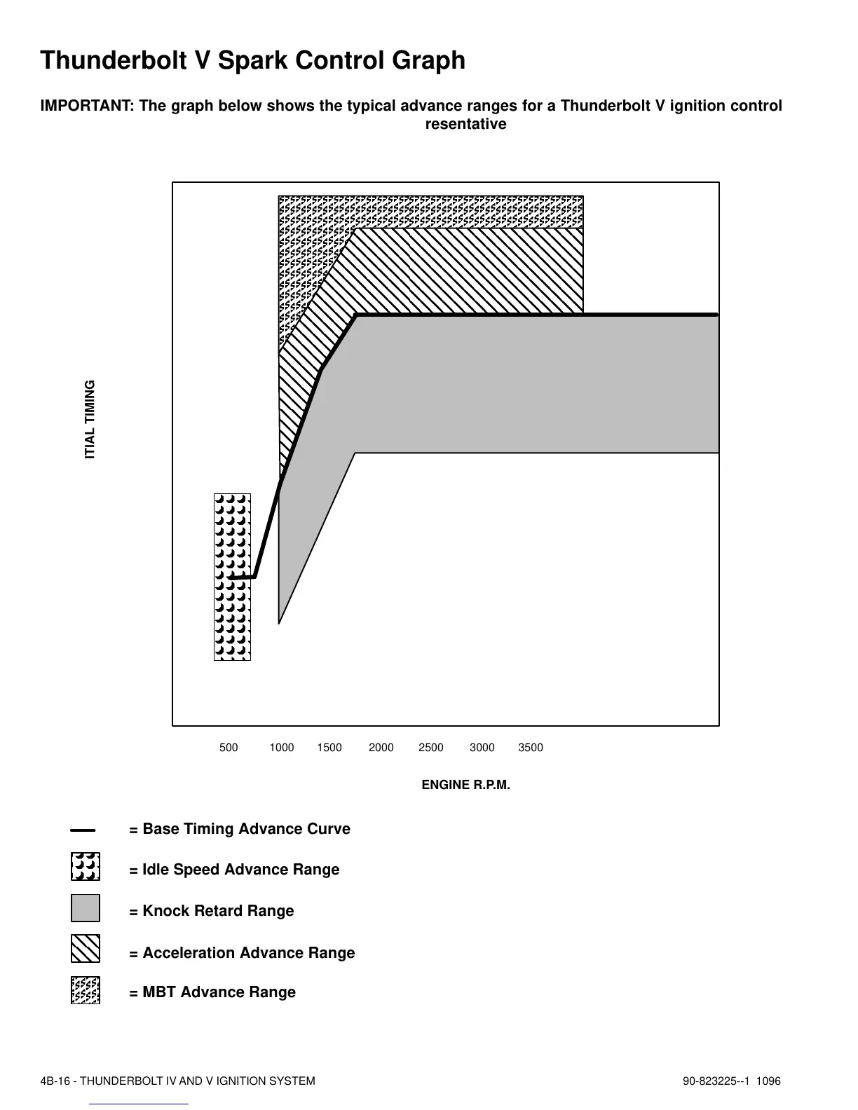
TOTAL SPARK ADVANCE
MINUS INITIAL TIMING
ENGINE R.P.M.
= Base Timing Advance Curve
= Idle Speed Advance Range
= Knock Retard Range
= Acceleration Advance Range
= MBT Advance Range
4B-16 - THUNDERBOLT IV AND V IGNITION SYSTEM 90-823225--1 1096
Thunderbolt V Spark Control Graph
IMPORTANT: The graph below shows the typical advance ranges for a Thunderbolt V ignition control
module. The numbers plotted on the graph are not representative of any particular model. It is only pres-
ented to provide an understanding of how the system functions.

 Loading...