8D-8 - DRIVE SHAFT / PROPELLER SHAFT MODELS 90-823225--1 1096
Installation
1. Install bearing support assembly (tailstock) on
transom plate using hardware as shown. Tighten
bolts until snug. DO NOT TORQUE BOLTS AT
THIS TIME.
IMPORTANT: The spherical washers MUST BE
positioned so that the rounded side of the wash-
ers are toward the bearing support assembly as
shown.
f
e
a
b
c
d
h
g
75279
a - Bolts 1/2-20 x 4 In. (102 mm) Long
b - Steel Washer (Flat)
c - Spherical Washer (Rounded On One Side)
d - Bearing Support
e - Spherical Washer (Rounded On One Side)
f - Nut 1/2-20
g - Transom Plate
h - Bearing Support (Tailstock)
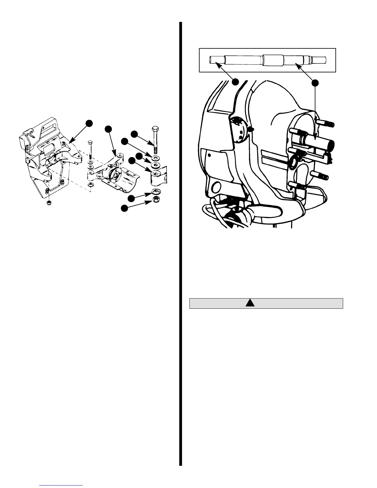
2. Insert solid end of Quicksilver Alignment Tool
through bearing in gimbal housing and into input
shaft splines of bearing support.
71401
a
b
Typical Stern Drive Unit Shown
a - Quicksilver Alignment Tool
b - Insert This End Of Alignment Tool Through Gimbal Hous-
ing Assembly
3. DO NOT remove alignment tool from gimbal
housing.
!
CAUTION
Both attaching bolts MUST BE struck firmly in
the following step to properly seat spherical
washers. If procedure is not followed, difficulty
in the installation of the stern drive may be expe-
rienced and subsequent damage to input bear-
ing may result.

 Loading...