3A-44 - ENGINES 90-823225--1 1096
Oil Pump
72146
1
4
5
6
9
11
2
3
12
8
7
10
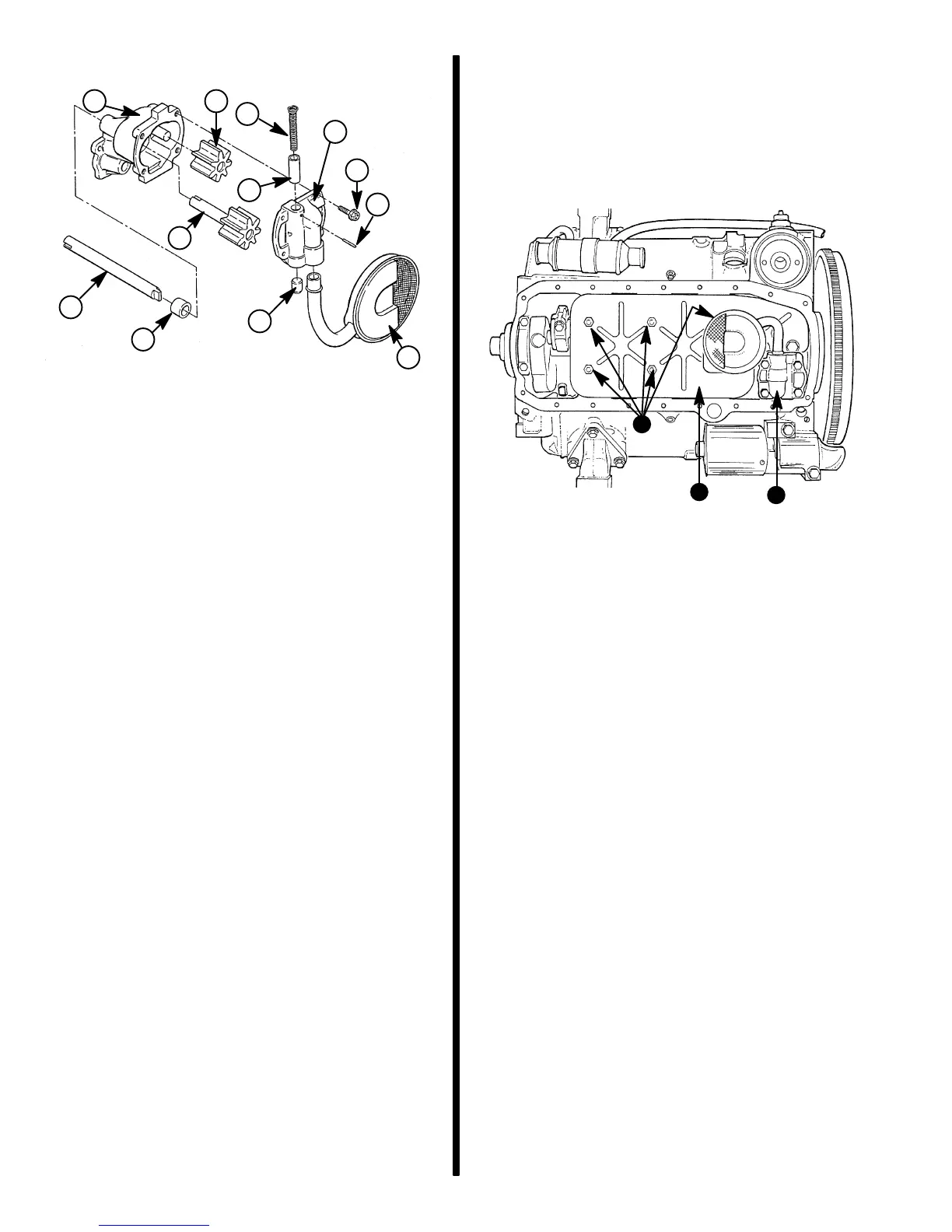
Oil Pump Assembly
1 - Extension Shaft
2 - Shaft Coupling
3 - Pump Body
4 - Drive Gear and Shaft
5 - Idler Gear
6 - Pick Up Screen and Pipe
7 - Pump Cover
8 - Pressure Regulator Valve
9 - Pressure Regulator Spring
10- Plug
11- Screws
The oil pump consists of two gears and a pressure
regulator valve enclosed in a two-piece housing. Oil
pump is driven by distributor shaft which is driven by
a helical gear on camshaft.
Removal
1. Remove oil pan as outlined.
2. Remove gasket carefully as the one-piece gas-
ket for the oil pan may be reused if still pliable and
not cracked, torn, etc.
3. Remove baffle.
72344
b
a
c
a - Nuts (5)
b - Baffle
c - Oil Pump
4. Remove oil pump
Disassembly
1. Remove pump cover.
IMPORTANT: Mark gear teeth for reassembly with
same teeth indexing.
2. Remove idler gear and drive gear from pump
body.
3. Remove retaining pin, spring, and pressure regu-
lator valve from pump cover.
IMPORTANT: Do not remove pickup screen and
pipe assembly, unless replacement is necessary.
Loss of press fit condition could result in an air
leak and loss of oil pressure.
IMPORTANT: Do not disturb pickup screen on
pipe. This is serviced as an assembly.
4. If pickup screen and pipe assembly requires re-
placement, mount pump in a soft-jawed vise and
extract pipe from pump.

 Loading...