CHARGING SYSTEM - 4C-790-823225--1 1096
5. Turn off accessories and reinstall coil wire. Start
engine and adjust engine speed to 1500-2000
RPM. Quickly observe ammeter. Reading should
be at least 30 amps.
6. If reading is low, stop engine and connect a jump-
er wire between alternator output terminal and
regulator terminal. Repeat Steps 4 and 5.
7. If reading is now within specifications, diodes are
faulty. Disassemble alternator and replace
rectifier as explained under “Alternator Repair,”
following, to determine if fault is in regulator or
alternator.
8. If reading is still low with jumper wire connected,
perform “Voltage Output Test,” following, to de-
termine if fault is in regulator or alternator.
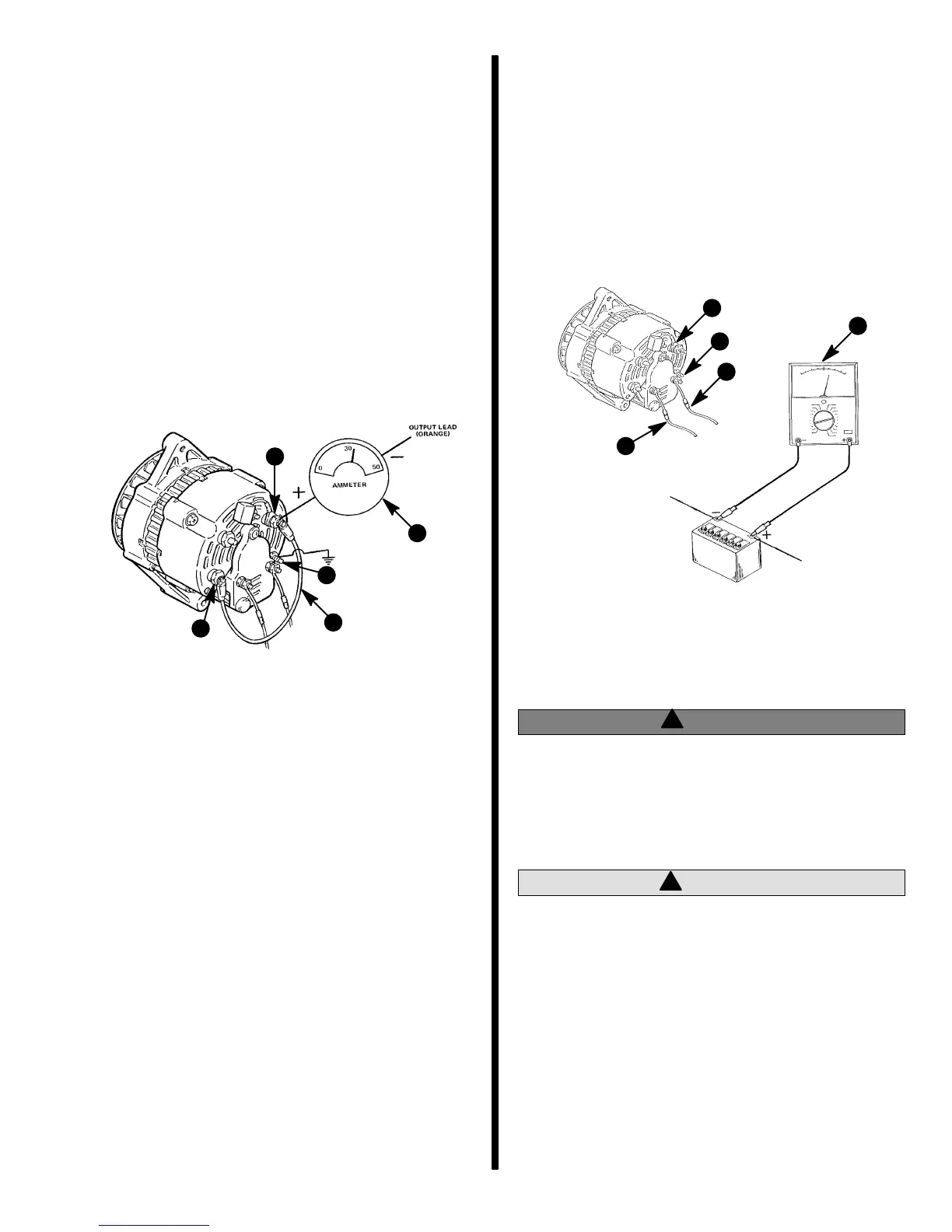
72787
b
c
d
a
e
a - Output Wire - ORANGE
b - Ammeter (0-50 Amps)
c - Jumper Lead
d - Regulator Lead
e - Ground
Voltage Output Test
Perform this test to determine if voltage regulator is
operating correctly, using a 0-20 volt DC voltmeter.
IMPORTANT: Battery MUST BE fully charged
(1.260 or above specific gravity) to obtain proper
voltage reading in this test. If necessary, charge
battery with a battery charger or allow engine to
run a sufficient length of time to fully charge bat-
tery before taking reading.
1. Connect positive (+) voltmeter lead to positive
battery terminal and negative (–) voltmeter lead
to negative terminal.
2. Start engine and run at fast idle until engine
reaches normal operating temperature. Adjust
engine speed to 1500-2000 RPM and observe
voltmeter for highest reading. Reading should be
between 13.9 and 14.7 volts.
3. If reading is high, check for a loose or dirty regula-
tor ground lead connection. If connection is good
(and sensing circuit checked out good in “Circuit-
ry Test”), voltage regulator is faulty and must be
replaced. Be sure to disconnect battery cables
before attempting to remove regulator.
72788
b
c
d
a
e
a - Output Wire - ORANGE
b - Excitation Wire - PURPLE
c - Sensing Wire - RED/PURPLE
d - Voltmeter (0-20 Volts)
e - Ground
!
WARNING
Be sure that engine compartment is well-venti-
lated and that there are no gasoline vapors pres-
ent (during the next steps) to prevent the possi-
bility of an explosion and/or fire, should a spark
occur.
!
CAUTION
DO NOT allow tie jumper wire to contact alterna-
tor end frame (in next step), as rectifier and diode
assembly may be damaged.

 Loading...