ELECTRONIC FUEL INJECTION (MULTI-PORT AND THROTTLE BODY) - 5E-1190-823225--1 1096
Digital Signals
Digital signals are also variable, but not continuously.
They can only be represented by distinct voltages
within a range. For example, 1 V, 2 V or 3 V would be
allowed, but 1.27 V or 2.65 V would not. Digital sig-
nals are especially useful when the information can
only refer to two conditions - “YES” and “NO,” “ON”
and “OFF,” or “High” and “Low.” This would be called
a digital binary signal. A digital binary signal is limited
to two voltage levels. One level is a positive voltage,
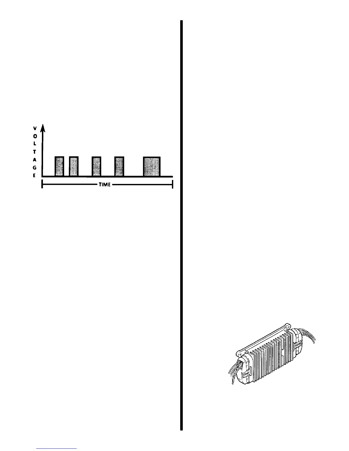
the other is no voltage (zero volts). As you can see
in the following figure, a digital binary signal is a
square wave.
Digital Binary Signal
LO
HI ON
OFF
YES
NO
The computer uses digital signals in a code that con-
tains only ones and zeros. The high voltage of the
digital signal represents a one (1), and no voltage
represents a zero (0). Each zero and each one is
called a bit of information, or just a “bit.” Eight bits to-
gether are called a “word.” A word, therefore, con-
tains some combination of eight binary code bits:
eight ones, eight zeros, five ones and three zeros,
and so on.
Binary code is used inside a computer and between
a computer and any electronic device that under-
stands the code. By stringing together thousands of
bits, computers can communicate and store an infi-
nite variety of information. To a computer that under-
stands binary, 11001011 might mean that it should re-
set engine RPM at a lower level. Although the
computer uses 8-bit digital codes internally and when
talking to another computer, each bit can have a
meaning.
SWITCH TYPES
Switched inputs (also known as discretes) to the
computer can cause one bit to change, resulting in in-
formation being communicated to the computer.
Switched inputs can come in two types: they are
“pull-up” and “pull-down” types. Both types will be
discussed.
With a pull-up type switch, the ECM will sense a volt-
age when the switch is CLOSED. With the pull-down
switch, the ECM recognizes the voltage when the
switch is OPEN.
Discretes can also be used to inform a computer of
FREQUENCY information.
PULSE COUNTERS
For the computer to determine frequency information
from a switched input, the computer must measure
the time between voltage pulses. As a number of
pulses are recorded in a set amount of time, the com-
puter can calculate the frequency. The meaning of
the frequency number can have any number of
meanings to the computer.
An example of a pulse counter type of input is the dis-
tributor reference pulse input. The computer can
count a train of pulses, a given number of pulses per
engine revolution, and determine the RPM of the en-
gine.
Engine Control Module (ECM)
The Engine Control Module (ECM) is the control cen-
ter of the fuel injection system. It constantly monitors
information from various sensors, and controls the
systems that affect engine performance.
The ECM also performs a diagnostic function check
of the system. It can recognize operational problems
and store a code or codes which identify the problem
areas to aid the technician in making repairs.
72801
Electronic Control Module (ECM)

 Loading...