MIE MODELS - VELVET DRIVE TRANSMISSIONS - 2E-590-823325--1 1096
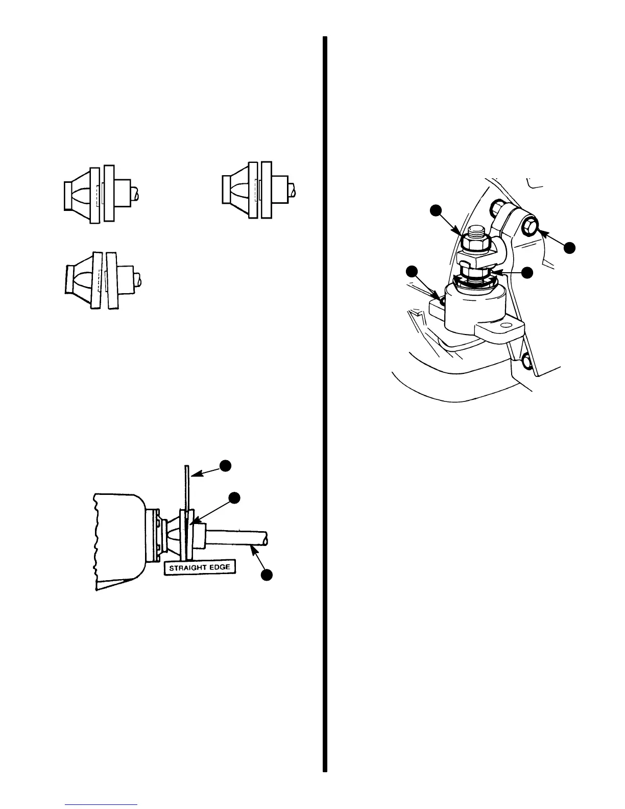
3. Check that coupling centerlines align, by butting
propeller shaft coupler against transmission out-
put flange. Shoulder on propeller shaft coupler
should engage recess on transmission output
flange face with no resistance.
NOTE: Some propeller shaft couplers may not have
a shoulder on mating face. On these installations,
use a straight edge to check centerline alignment.
72597
INCORRECT
CORRECT
INCORRECT
IMPORTANT: Remote V-Drive Models: refer to re-
mote V-drive manufacturer’s instructions for
drive shaft (between transmission and remote
V-drive) alignment.
4. Check for angular misalignment, by hand holding
coupling faces tightly together; check for a gap
between faces with a .003 in. (0.07 mm) feeler
gauge at 90° intervals.
72598
a - Feeler Gauge
b - Transmission Coupling
c - Propeller Shaft
b
c
a
5. If coupling centerlines are not aligned or if cou-
pling faces are more than .003 in. (0.07 mm) out
of parallel, adjust engine mounts as follows:
a. TO ADJUST ENGINE UP OR DOWN: Loos-
en locking nut on mounts requiring adjust-
ment and turn both front mount or rear mount
adjusting nuts equally.
IMPORTANT: Both front mount (or rear mount)
adjusting nuts must be turned equally to keep en-
gine level from side to side.
72594
c
a
d
b
a - Locking Nut
b - Adjusting Nut
c - Clamping Screws and Nuts, with Lockwashers
(Two Each on Some Mounts)
d - Slot Forward (if So Designed - NOT Slotted on
This Style Rear Mount)
Typical Mount
b. TO MOVE ENGINE TO THE LEFT OR
RIGHT: Loosen clamping screw and nut on all
four mount brackets; move engine to the left
or right as necessary to obtain proper align-
ment. On mounts which do have a slotted
hole, a small amount of adjustment can be
obtained with slot on front end of mounts.
Loosen lag screws (which fasten mounts to
engine bed) and move engine, as required.
Tighten lag screws securely.
c. After engine has been properly aligned:
Tighten engine mount nuts securely, and be
certain to bend one of the tabs on the tab
washer down onto flat of mount adjusting nut.
Torque clamping screws and nuts to 50 lb. ft.
(68 N·m).

 Loading...