CHARGING SYSTEM - 4C-1990-823225--1 1096
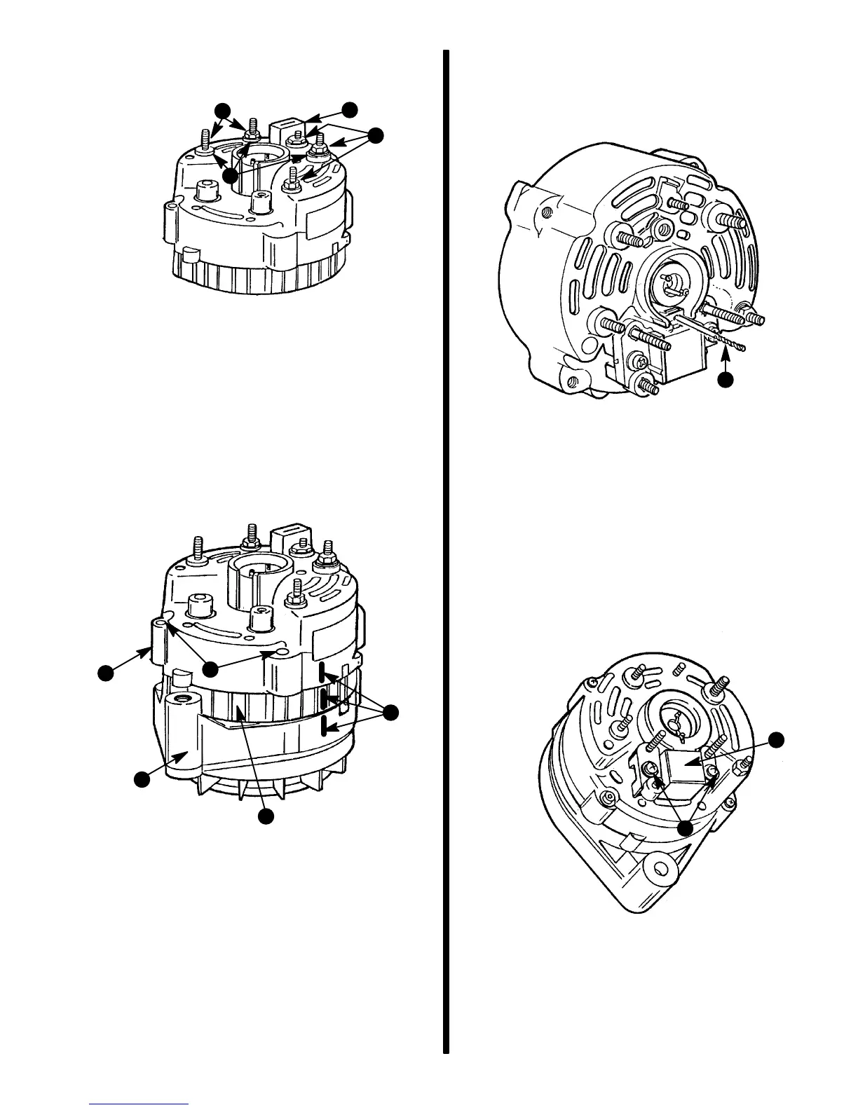
7. Position stator down with rear end frame up and
reinstall insulators, nuts and condenser.
72561
c
a
b
b
a - Insulators (3)
b - Nuts (5) - ONE REMOVED
c - Condenser
8. Position rear end frame and stator assembly over
front end frame and rotor assembly and align
scribe marks on each (scribed during disassem-
bly). Hand-press end frames together, then in-
stall four screws. Tighten screws securely.
72561
b
c
a
e
d
a - Rear End Frame
b - Stator
c - Front End Frame
d - Scribe Marks
e - Insert Screws (4) (Two Hidden)
9. Depress brushes flush with top of brush holder
and insert a #54, .050 in. drill bit or smaller into
hole in brush holder to hold brushes compressed
during reassembly.
72836
a
a - Drill Bit
NOTE: Rubber gasket shown removed for clarity.
10. Install brush/regulator assembly in rear end
frame cavity and secure with two mounting
screws, as shown. Tighten screws securely. Re-
move drill bit to release brushes against slip
rings.
72837
a
b
a - Brush / Regulator Assembly
b - Mounting Screws

 Loading...