4F-30 - WIRING DIAGRAMS 90-823225--1 1096
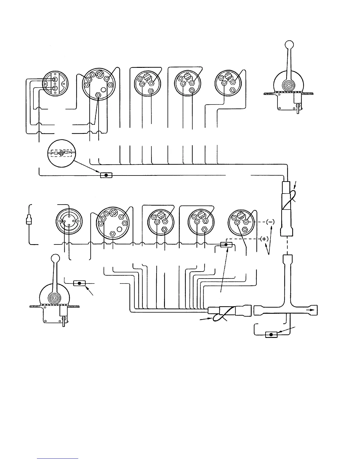
DUAL STATION WIRING USING A NEUTRAL SAFETY SWITCH IN ENGINE WIRING HARNESS
72942
STOP-START
PANEL
TACHOMETER
OIL
PRESSURE
WATER
TEMPERATURE
BATTERY
METER
IGNITION
SWITCH
TACHOMETER
OIL
PRESSURE
WATER
TEMPERATURE
BATTERY
METER
SECONDARY STATION
PRIMARY STATION
BRN/WHT
TO
ENGINE
PUR
GRY
BLK
YEL/RED
NOTE 3
PUR
PUR
GRY
BLK
BLK
LT. BLU
BLK
PUR
TAN
PUR
BLK
RED/PUR
ORN
20 AMP
FUSE
PUR
PUR
GRY
BLK
BLK
PUR
LT. BLU
BLK
PUR
TAN
ORN
RED/PUR
PUR
BLK
NOTE 2
NOTE 3
NOTE 1
YEL/RED
YEL/RED
NOTE 3
NOTE 3
BRN/WHT
NOTE 1
YEL/RED
YEL/RED
SEND
SEND
SEND
LT
LT
LT
LT
SW
12V
12V
12V
12V
GND
UNSW
SIG
GND
GND
GND
B
S
I
SEND SEND SEND
LT
LT
LT
LT
SW
12V
12V
12V
12V
GND
UNSW
SIG
GND GND
GND
NOTE 1: Brown/white wire is taped back at instrument end. If installing on boat that is equipped with MerCruiser
Stern Drive, brown/white wire is connected to trim sender terminal block. If installing on Mercruiser Inboard,
brown/white wire is taped back at engine end, or it may be used for an accessory (limit 5 amps).
NOTE 2: An accessory fuse panel may be connected at this location. The combined current draw of the primary
station and secondary station MUST NOT exceed 35 amps.
NOTE 3: Connect wires together with screw and hex nut. Apply Liquid Neoprene to connection and slide rubber
sleeve over connection.

 Loading...