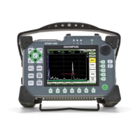
910-269-EN, Rev. B, June 2011
List of Figures 333
List of Figures
Figure 1-1 Overview of the EPOCH 1000i hardware ...................................................... 20
Figure 1-2 The EPOCH 1000i hardware user interface elements .................................. 21
Figure 1-3 General purpose keys and knob ...................................................................... 22
Figure 1-4 [F<n>] and [P<n>] keys pointing to software buttons ................................... 23
Figure 1-5 The English direct-access keypad with model differences ......................... 25
Figure 1-6 Front panel indicator lights .............................................................................. 27
Figure 1-7 Location of the conventional transducer connectors .................................... 28
Figure 1-8 The connector for the phased array (PA) probe ............................................ 29
Figure 1-9 Phased array connection cover ........................................................................ 31
Figure 1-10 The ALARMS and ANALOG OUT connectors ............................................ 32
Figure 1-11 Battery compartment cover .............................................................................. 33
Figure 1-12 The connectors behind the computer connection compartment door ....... 34
Figure 1-13 Tilting angles using the bottom and rear stands ........................................... 36
Figure 2-1 Location of the EPOCH 1000 power key and indicator ............................... 40
Figure 2-2 The Beam setup page appearing at startup when a PA probe is
connected ............................................................................................................ 41
Figure 2-3 The AC adaptor plug ........................................................................................ 42
Figure 2-4 The battery charge indicator ............................................................................ 43
Figure 2-5 Opening the battery compartment .................................................................. 46
Figure 3-1 Exploded view of the software main display elements ............................... 50
Figure 3-2 Overview of the menu system in UT operation mode ................................. 51
Figure 3-3 The menu indicator (1/5) .................................................................................. 51
Figure 3-4 Concise convention to identify menu elements ............................................ 53
Figure 3-5 The focus is on the element appearing yellow .............................................. 54
Figure 3-6 Message bar with a file name example ........................................................... 55
Figure 3-7 Message bar with a message example ............................................................ 55
Figure 3-8 Example of software indicators ....................................................................... 56
Figure 3-9 Example of the Angle and Gain permanent parameters ............................. 57
Figure 3-10 Example of the Range and Delay direct-access parameters ........................ 57
Figure 3-11 Example of measurement reading boxes with their icons ........................... 57
Downloaded from ManualsNet.com search engine

 Loading...