4-19
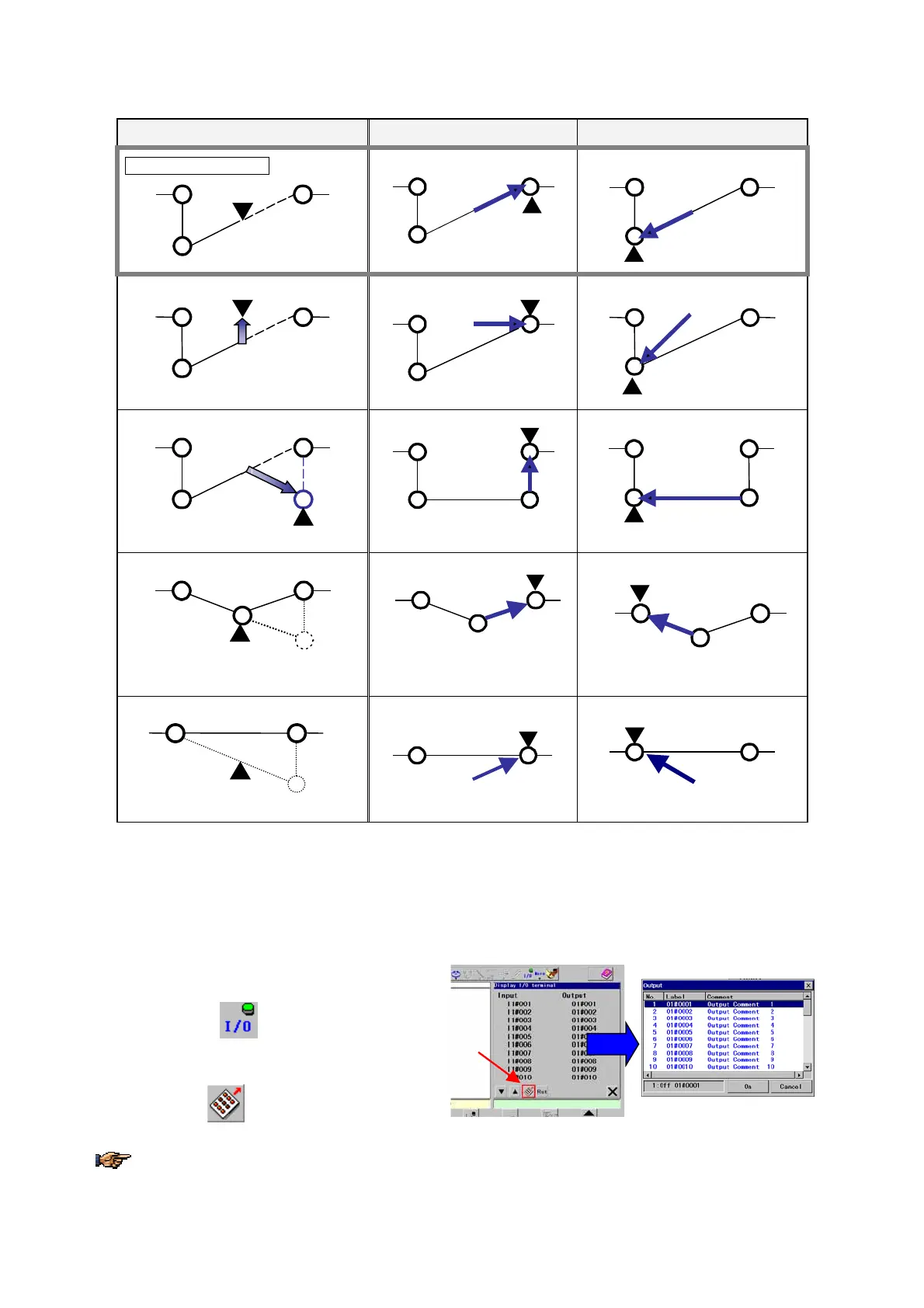
• Stop the robot between teaching points (4 and 5) and then edit the point
Manual edit Trace forward Trace backward
Original robot motion
4
5
3
4
5
3
4
5
3
Manually move the robot
4
5
3
(Moves the robot manually)
4
5
3
4
5
3
Add a point
4
5
3
6
(new)
(Add a teaching point (6) between 4 and 5)
4
6
3
5
4
6
3
5
Change position of a point
(4)
3
5
4(new)
(Change the teaching point.)
3
5
4
3
5
4
Delete a point
5
3
(4)
(Delete a teaching point (4))
5
3
5
3
(▼ indicates location of the robot control point after exit or trace forward/backward.)
4-13. I/O monitor
It displays user input/output state when the robot is in the hold state. It is possible to change ON/OFF state of outputs
with this display. (This I/O monitor function is available when the mode select switch is in the TEACH position.)
1. Place the mode select switch in the Teach
position.
2. Turn ON the
In/Out
icon on the menu bar to
display the I/O monitor screen in the right pane.
3. Turn ON the
icon to display the box to
change OUTPUT state.
The robot does not retain the ON/OFF state of OUTPUT terminals if ON/OFF state of an OUTPUT terminal is
changed using this I/O monitor function while the robot is in the hold state.