10-3
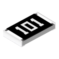
10-2-3. Definition of L1 type tool offset
• It uses 4 parameters, L1, L2, L3 and TW, to determine the tool
offset.
• When the BW axis is at –90 degrees, define the intersection
point of RW-axis and TW-axis as “point P” and the plane on
which the control point travels by moving only the TW-axis as
“plane Q”.
L1
Distance (in millimeters) between point P and plane Q.
L2
Distance (in millimeters) between the control point and the
TW rotation center.
L3
Distance (in millimeters) between the intersection point the
extension of the flange surface and the extension of the tool
direction intersects and the TW-axis rotation center.
TW Tool setting angle (in degree) measured from TW=0
* For details of each parameter, refer to manual of applied
equipment.
TW
Plane of L1,
L2 and L3
Plane Q
TW rotation
center
Flange
surface
+
L
2
L1
L3
Point P
Control
point
L2
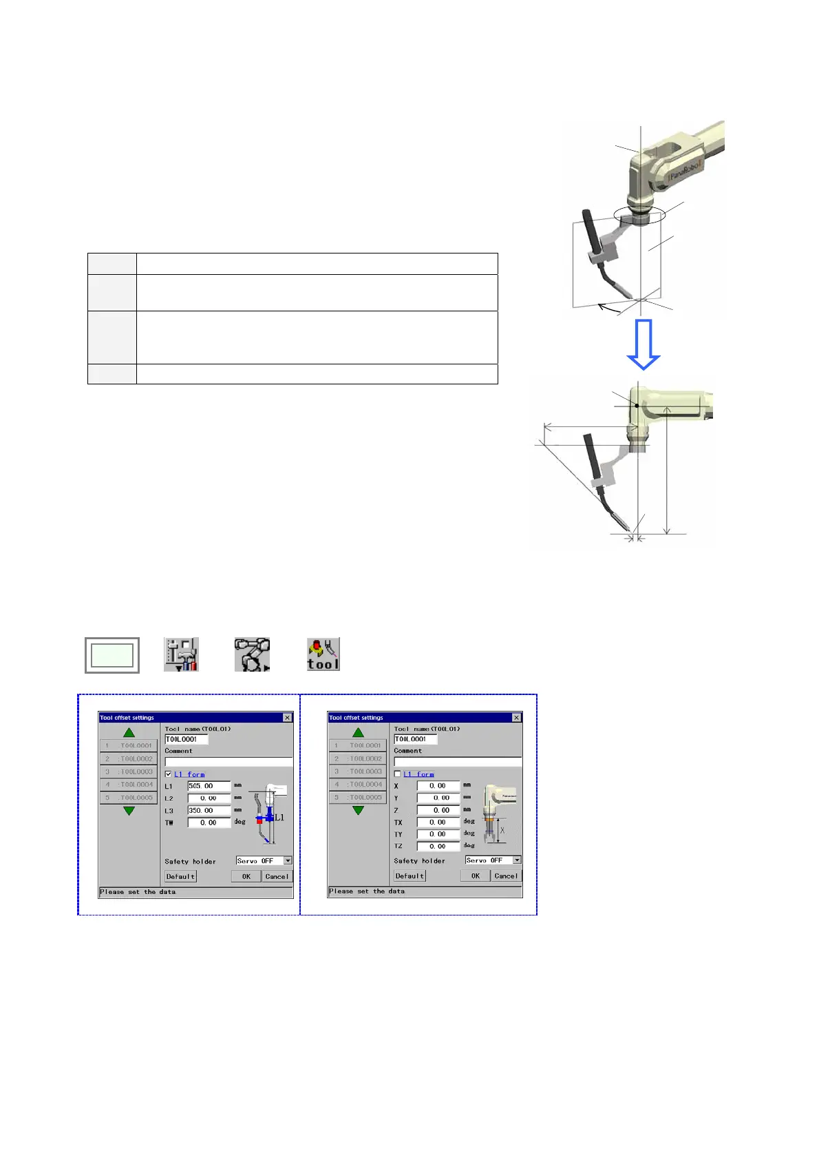
10-2-4. Setting procedure
Set the control point of the manipulator on which an interpolation movement of the robot is controlled to be operated.
Click
>>
Set
>>
Robot
>>
Tool
(Welding robots)
Î
(Handling robots)
Î
[Tool name] Type the tool name (the
identifier of each tool) you want to work
on. The Tool name can have up to 20
characters.
[Comment] Provides a space for you to
add comment about the tool.
Comments can have up to 20
characters.
[L1 form] Click this box to apply the L1
form to set parameters.
Clear this box to apply the XYZ form.
[Safety holder] Specifies whether the
robot should be in the [Hold] state or in
the [Servo OFF] state when the safety
holder activates.
[Default] Resets the settings in this
dialog box to the factory settings at
shipment.