10-10
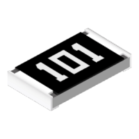
To identify the data as variable name, fill in the variable name box
and the click the OK button.
7.
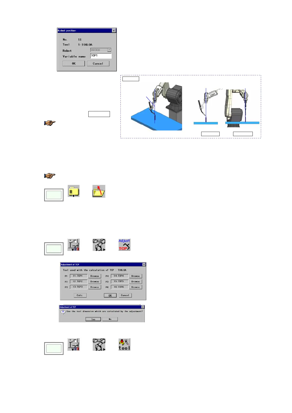
<Position 2>
Then move the Y-axis of the tool
coordinate system to align the
directions of the adjustment jig and
of the TW axis rotation center as the
second position on the tool X-Z
plane. (See the figre Position 2.)
Only Y-axis of the tool
coordinate system is operable.
Position 2
Align the directions of the adjustment jig and of the TW axis rotation center.
TW axis
rotation center
Side view Front view
Move the cursor to the variable for the Position 2, and then press the ENTER key.
8. Rotate the Y-axis again to change the position for the third position on the tool X-Z plane. <Position 3>
9. As for Positions 4 to 6, teach position on the tool X-Y plane.
For Positions 5 and 6, only Z-axis of the tool coordinate system is operable.
10.
Click
>>
File
>>
Close
to close the list of the robot variables.
Then a dialog box to confirm updating the adjustment appears. Click the OK button.
(2) TCP offset value calculation
1.
Click
>>
Set
>>
Robot
>>
TCP
adjust
Î
If all positions has stored properly, the preset
variable names are indicated in the P1 to P6 boxes.
Then click the Calc. button.
2.
Click the OK button, then the dialog box to confirm
the adjustment appears. Click the Yes button to
complete the adjustment.
3. Check the adjusted tool offset value.
Click
>>
Set
>>
Robot
>>
Tool