RL78/G10 CHAPTER 6 TIMER ARRAY UNIT
R01UH0384EJ0311 Rev. 3.11 180
Dec 22, 2016
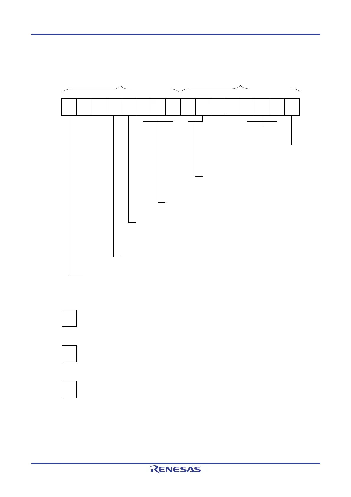
Figure 6-58. Example of Set Contents of Registers to Measure Input Signal High-/Low-Level Width (1/2)
(a) Timer mode register 0n (TMR0nH, TMR0nL)
TMR0nH TMR0nL
7 6 5 4 3 2 1 0 7 6 5 4 3 2 1 0
TMR0n
CKS0n1
1/0
0
0
CCS0n
0
M/S
Note
0
STS0n2
0
STS0n1
1
STS0n0
0
CIS0n1
1
CIS0n0
1/0
0
0
MD0n3
1
MD0n2
1
MD0n1
0
MD0n0
0
Operation mode of channel n
110B: Capture & one-count
Setting of operation when counting is started
0: Does not generate INTTM0n when
counting is started.
Selection of TI0n pin input edge
10B: Both edges (to measure low-level width)
11B: Both edges (to measure high-level width)
Start trigger selection
010B: Selects the TI0n pin input valid edge.
Setting of MASTER0n bit (Channel 2)
0: Independent channel operation
Setting of SPLIT0n bit (Channel 1, 3)
0: 16-bit timer
Count clock selection
0: Selects operation clock (f
MCK).
Operation clock (f
MCK) selection
0: Selects CK00 as operation clock of channel n.
1: Selects CK01 as operation clock of channel n.
(b) Timer output register 0 (TO0)
Bit n
TO0
TO0n
0
0: Outputs 0 from TO0n.
(c) Timer output enable register 0 (TOE0)
Bit n
TOE0
TOE0n
0
0: Stops the TO0n output operation by counting operation.
(d) Timer output level register 0 (TOL0)
Bit n
TOL0
TOL0n
0
0: Setting is invalid because master channel output mode is set (TOM0n = 0).
Note TMR02: MASTER0n bit
TMR01, TMR03: SPLIT0n bit
TMR00: 0 fixed
Remark n: Channel number
n = 0, 1 (for 10-pin products); n = 0 to 3 (for 16-pin products)

 Loading...


