RL78/G10 CHAPTER 6 TIMER ARRAY UNIT
R01UH0384EJ0311 Rev. 3.11 217
Dec 22, 2016
Remarks 1. n: Channel number (n = 0)
p: Slave channel number 1, q: Slave channel number 2
n < p < q ≤ 3 (Where p and q are consecutive integers greater than n)
2. TS0n, TS0p, TS0q: Bit n, p, q of timer channel start register 0 (TS0)
TE0n, TE0p, TE0q: Bit n, p, q of timer channel enable status register 0 (TE0)
TCR0n, TCR0p, TCR0q: Timer count registers 0n, 0p, 0q (TCR0n, TCR0p, TCR0q)
TDR0n, TDR0p, TDR0q: Timer data registers 0n, 0p, 0q (TDR0n, TDR0p, TDR0q)
TO0n, TO0p, TO0q: TO0n, TO0p, and TO0q pins output signal
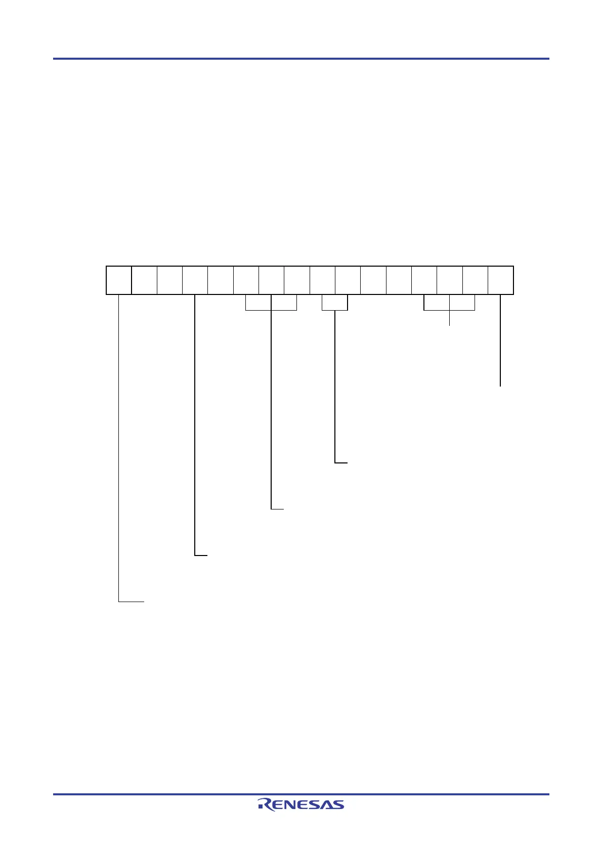
Figure 6-81. Example of Set Contents of Registers for Multiple PWM Output Function (Master Channel) (1/2)
(a) Timer mode register 00 (TMR00)
15 14 13 12 11 10 9 8 7 6 5 4 3 2 1 0
TMR00
CKS001
1/0
0
0
CCS00
0
1
STS002
0
STS001
0
STS000
0
CIS001
0
CIS000
0
0
0
MD003
0
MD002
0
MD001
0
MD000
1
Operation mode of channel 0
000B: Interval timer
Setting of operation when counting is started
1: Generates INTTM00 when counting is
started.
Selection of TI00 pin input edge
00B: Sets 00B because these are not used.
Start trigger selection
000B: Selects only software start.
Count clock selection
0: Selects operation clock (f
MCK).
Operation clock (f
MCK) selection
0: Selects CK00 as operation clock of channel 0.
1: Selects CK01 as operation clock of channel 0.

 Loading...


