RL78/G10 CHAPTER 6 TIMER ARRAY UNIT
R01UH0384EJ0311 Rev. 3.11 219
Dec 22, 2016
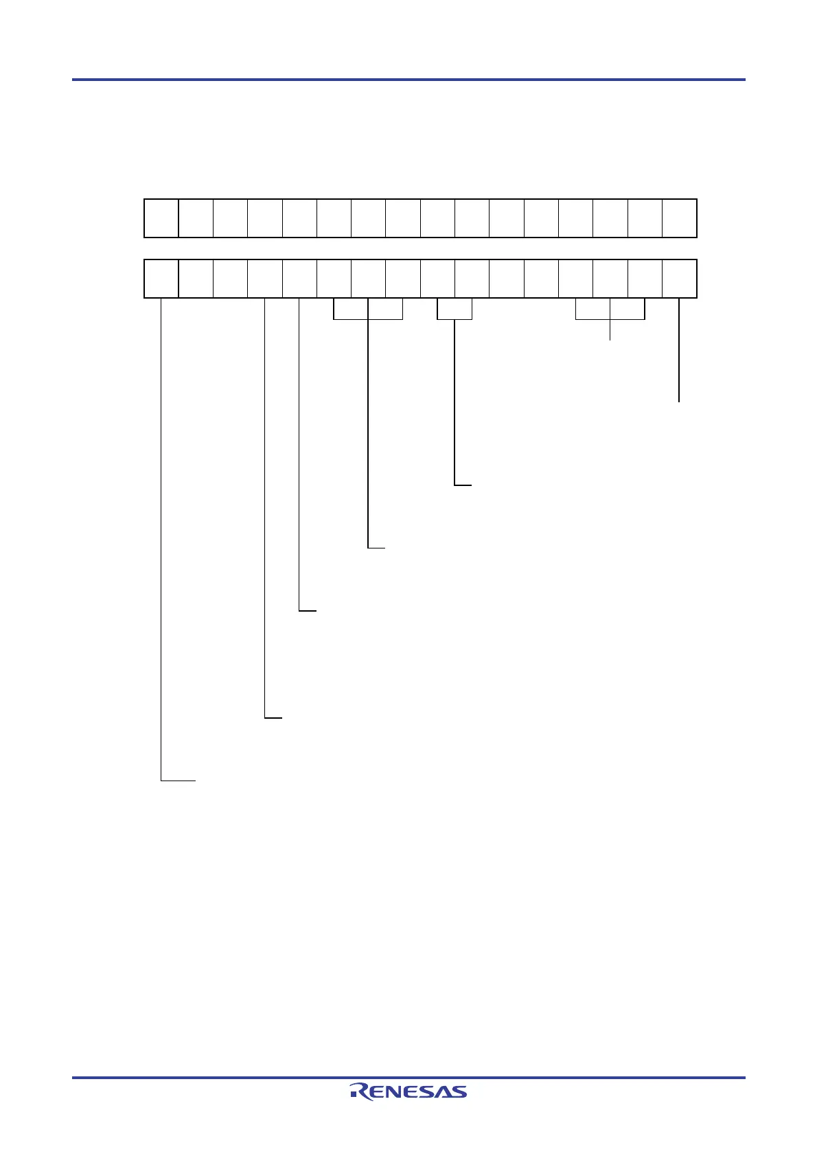
Figure 6-82. Example of Set Contents of Registers for Multiple PWM Output Function (Slave Channel)
(Output Two Types of PWMs) (1/2)
(a) Timer mode register 0p, 0q (TMR0p, TMR0q)
15 14 13 12 11 10 9 8 7 6 5 4 3 2 1 0
TMR0p
CKS0p1
1/0
0
0
CCS0p
0
M/S
Note
0
STS0p2
1
STS0p1
0
STS0p0
0
CIS0p1
0
CIS0p0
0
0
0
MD0p3
1
MD0p2
0
MD0p1
0
MD0p0
1
15 14 13 12 11 10 9 8 7 6 5 4 3 2 1 0
TMR0q
CKS0q1
1/0
0
0
CCS0q
0
M/S
Note
0
STS0q2
1
STS0q1
0
STS0q0
0
CIS0q1
0
CIS0q0
0
0
0
MD0q3
1
MD0q2
0
MD0q1
0
MD0q0
1
Operation mode of channel p, q
100B: One-count mode
Start trigger during operation
1: Trigger input is valid.
Selection of TI0p and TI0q pins input edge
00B: Sets 00B because these are not used.
Start trigger selection
100B: Selects INTTM00 of master channel.
Setting of MASTER0p and MASTER0q bits (Channel 2)
0: Slave channel
Setting of SPLIT0p and SPLIT0q bits (Channel 1, 3)
0: 16-bit timer
1: 8-bit timer
Count clock selection
0: Selects operation clock (f
MCK).
Operation clock (f
MCK) selection
0: Selects CK00 as operation clock of channel p, q.
1: Selects CK01 as operation clock of channel p, q.
* Make the same setting as master channel.
Note TMR02: MASTER0p and MASTER0q bits
TMR01, TMR03: SPLIT0p and SPLIT0q bits
Remark p: Channel number of slave channel 1, q: Channel number of slave channel 2
0 < p < q ≤ 3 (Where p and q are consecutive integers greater than 0)

 Loading...


