RL78/G10 CHAPTER 6 TIMER ARRAY UNIT
R01UH0384EJ0311 Rev. 3.11 221
Dec 22, 2016
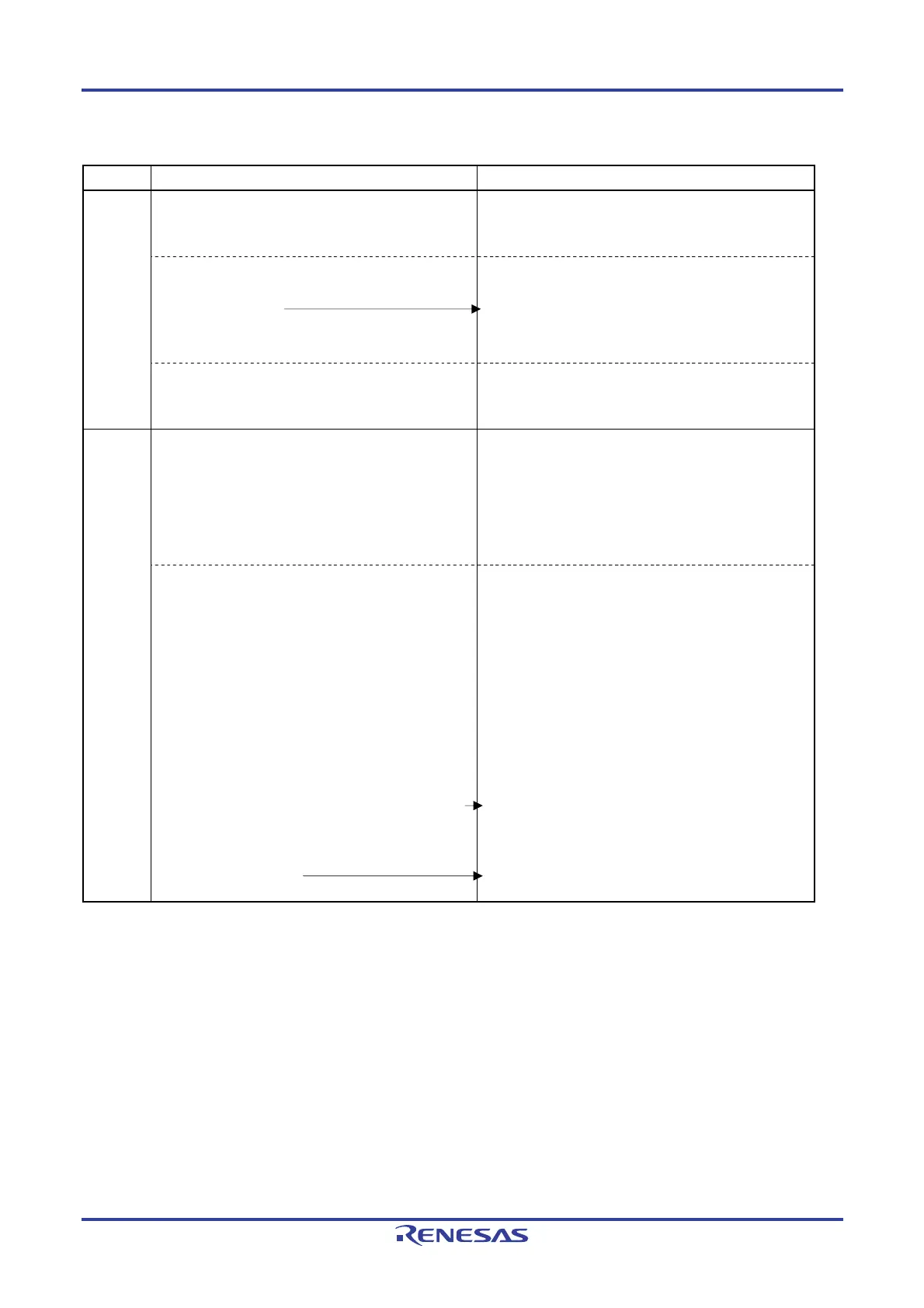
Figure 6-83. Procedure for Using Multiple PWM Output Function (Output Two Types of PWMs) (1/2)
Software Operation Hardware Status
TAU
default
setting
Power-off status
(Clock supply is stopped and writing to SFR of the TAU
is disabled.)
Sets the TAU0EN bit of peripheral enable register 0
(PER0) to 1 (when the TAU0EN bit is 0, read/write
operation is disabled).
Power-on status. Each channel stops operating.
(Clock supply is started and writing to SFR of the TAU is
enabled.)
Sets timer clock select register 0 (TPS0).
Determines operating clock (CK00 and CK01) for each
channel.
Channel
default
setting
Sets timer mode registers 00, 0p, 0q (TMR00, TMR0p,
TMR0q) (determines operation mode for each channels).
Sets an interval (period) value of the master channel and
a duty factor of the slave channels to the timer data
registers 00, 0p, and 0q (TDR00, TDR0p, and TDR0q)
(for the access procedure to the TDR0nH and TDR0nL
registers, see 6.2.2 Timer data register 0n (TDR0n)).
Channel stops operating.
(Clock is supplied and some power is consumed.)
Sets master channel.
Clears the target bit of the timer output mode register
0 (TOM0) to 0 (master channel output mode).
Clears the target bit of the TOL0 register to 0.
Clears the target bit of the timer output enable register
0 (TOE0) to 0.
Sets slave channel.
Sets the target bit of the timer output mode register 0
(TOM0) to 1 (slave channel output mode).
Sets the target bit of the TOL0 register.
Sets the TO0p and TO0q bits and determines default
level of the TO0p and TO0q outputs.
Sets the TOE0p and TOE0q bits to 1 and enables
TO0p and TO0q outputs based on count operation.
Clears the port register and port mode register to 0.
(output mode is set.)
The TO0p and TO0q pins go into Hi-Z state.
(The port mode register is in output mode.)
TO0p and TO0q do not change because channels stop
operating. (The TO0p pin is not affected even if the TO0p
or TO0q bit is modified).
The levels set in the TO0p and TO0q bits are output from
the TO0p and TO0q pins.
Remark p: Channel number of slave channel 1, q: Channel number of slave channel 2
n < p < q ≤ 3 (Where p and q are a consecutive integer greater than n)

 Loading...


