RL78/G10 CHAPTER 13 SERIAL INTERFACE IICA
R01UH0384EJ0311 Rev. 3.11 457
Dec 22, 2016
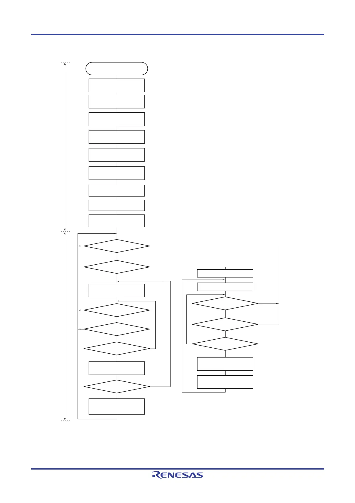
Figure 13-29. Slave Operation Flowchart (1)
Ye s
Ye s
Ye s
Ye s
Ye s
Ye s
Ye s
No
No
No
No
No
No
WREL0 = 1
SPIE0 = 1
ACKD0 = 1?
No
Ye s
No
Ye s
No
STAR
T
Communication
mode flag = 1?
Communication
mode flag = 1?
Communication
direction flag = 1?
Ready flag = 1?
Communication
direction flag = 1?
Reading IICA0
Clearing ready flag
Clearing ready flag
Communication
direction flag = 1?
Clearing communication
mode flag
WREL0 = 1
Writing IICA0
SVA0 ← XXH
Sets a local address.
IICWL0, IICWH0 ← XXH
Selects a t
Release the serial interface IICA0 from the reset status and start clock supply.
ransfer clock.
IICF0 ← 0XH
Setting IICRSV0
Sets a start condition.
Starts
transmission.
Starts
reception.
Communication
mode flag = 1?
Ready flag = 1?
Setting po
Setting PER0 register
rt
Setting port
Communication processing
Initial setting
Setting of the port used alternatively as the pin to be used.
First, set the port to input mode and the output latch to 0
Set the port from input mode to output mode and enable the output of the I
2
C bus
IICCTLn0 ← 0XX011XXB
ACKE0 = WTIM0 = 1, SPI0 = 0
IICCTL00 ← 1XX011XXB
IICE0 = 1
Setting IICCTL01
(see 13.3.8 Registers controlling port functions of IICA serial input/output pins
(see 13.3.8 Registers controlling port functions of IICA serial input/output pins
Remark Conform to the specifications of the product that is in communication, regarding the transmission and
reception formats.

 Loading...


