RL78/G10 CHAPTER 24 ELECTRICAL SPECIFICATIONS
R01UH0384EJ0311 Rev. 3.11 591
Dec 22, 2016
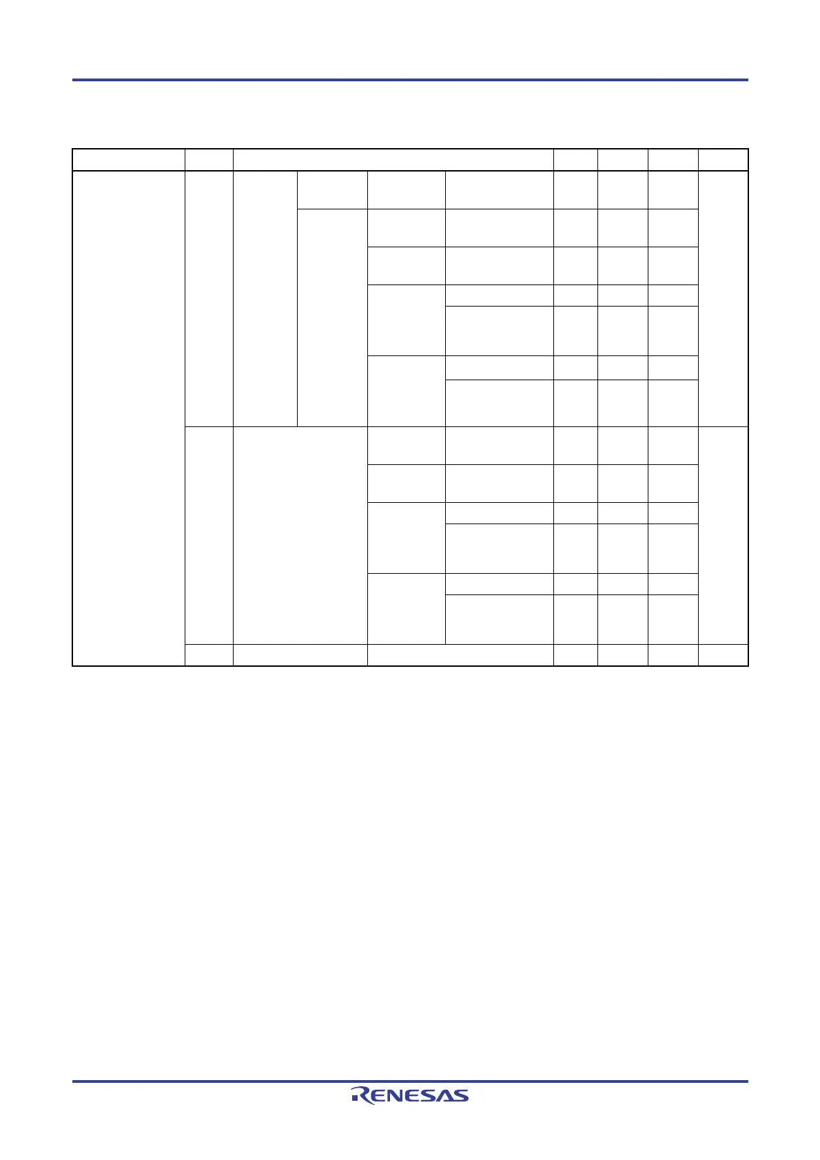
(2) Flash ROM: 4 KB of 10-pin products, and 16-pin products
(T
A = −40 to +85°C, 2.0 V ≤ VDD ≤ 5.5 V, VSS = 0 V)
Parameter Symbol Conditions MIN. TYP. MAX. Unit
Supply current
Note 1
IDD1
Operating
mode
Basic
operation
f
IH = 20 MHz
Note 4
V
DD = 3.0 V, 5.0 V 0.92 mA
Normal
operation
fIH = 20 MHz
Note 4
V
DD = 3.0 V, 5.0 V 1.59 2.14
fIH = 5 MHz
Note 4
V
DD = 3.0 V, 5.0 V 0.87 1.20
fMX = 20 MHz
Notes 5, 6
VDD = 3.0 V,
5.0 V
Square wave input 1.43 1.93
Resonator
connection
1.54 2.13
fMX = 5 MHz
Notes 5, 6
VDD = 3.0 V,
5.0 V
Square wave input 0.67 1.02
Resonator
connection
0.72 1.12
IDD2
Note 2
HALT mode
f
IH = 20 MHz
Note 4
V
DD = 3.0 V, 5.0 V 360 900 µA
fIH = 5 MHz
Note 4
V
DD = 3.0 V, 5.0 V 310 660
fMX = 20 MHz
Notes 5, 6
VDD = 3.0 V,
5.0 V
Square wave input 200 700
Resonator
connection
300 900
fMX = 5 MHz
Notes 5, 6
VDD = 3.0 V,
5.0 V
Square wave input 100 440
Resonator
connection
150 540
IDD3
Note 3
STOP mode VDD = 3.0 V 0.61 2.25 µA
Notes 1. Total current flowing into V
DD, including the input leakage current flowing when the level of the input pin is
fixed to V
DD or VSS. The values below the MAX. column include the peripheral operation current. However,
not including the current flowing into the A/D converter, comparator (16-pin products only), I/O port, and on-
chip pull-up/pull-down resistors.
2. During HALT instruction execution by flash memory.
3. Not including the current flowing into the 12-bit interval timer and watchdog timer.
4. When the high-speed system clock is stopped.
5. When the high-speed on-chip oscillator is stopped.
6. 16-pin products only
Remarks 1. f
IH: High-speed on-chip oscillator clock frequency
2. f
MX: High-speed system clock frequency (X1 clock oscillator frequency or external main system clock
frequency)
3. Temperature condition of the typical value is T
A = 25°C

 Loading...


