RL78/G10 CHAPTER 24 ELECTRICAL SPECIFICATIONS
R01UH0384EJ0311 Rev. 3.11 592
Dec 22, 2016
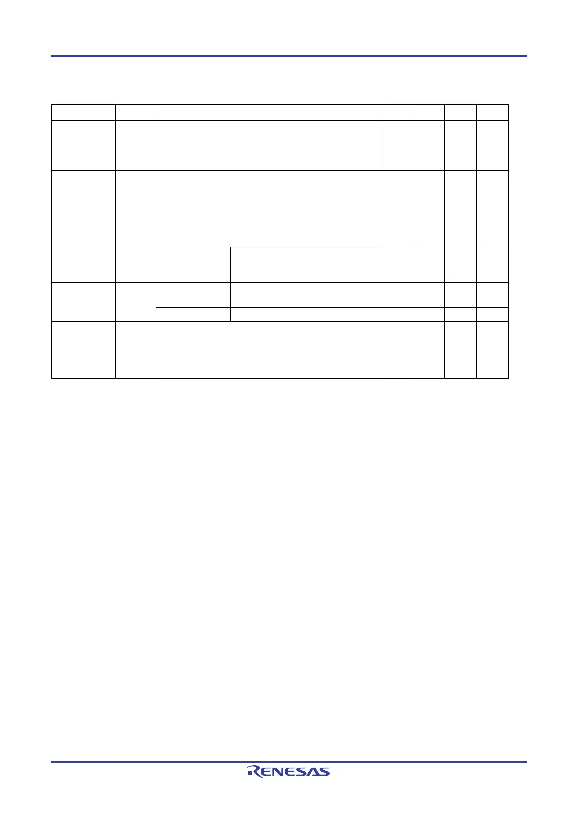
(3) Peripheral Functions (Common to all products)
(T
A = −40 to +85°C, 2.0 V ≤ VDD ≤ 5.5 V, VSS = 0 V)
Parameter Symbol Conditions MIN. TYP. MAX. Unit
Low-speed on-
chip oscillator
operating
current
I
FIL
Note 1
0.30 μA
12-bit interval
timer operating
current
I
TMKA
Notes 1, 2, 3
0.01 μA
Watchdog timer
operating
current
I
WDT
Notes 1, 4
0.01 μA
A/D converter
operating
current
IADC
Notes 1, 5
When conversion
at maximum speed
V
DD = 5.0 V 1.30 1.90 mA
VDD = 3.0 V 0.50 mA
Comparator
operating
current
ICMP
Notes 1, 6
In high-speed
mode
V
DD = 5.0 V 6.50 μA
In low-speed mode VDD = 5.0 V 1.70 μA
Internal
reference
voltage
operating
current
IVREG
Note 1
10 μA
Notes 1. Current flowing to V
DD.
2. When high speed on-chip oscillator and high-speed system clock are stopped.
3. Current flowing only to the 12-bit interval timer (excluding the operating current of the low-speed on-chip
oscillator). The supply current of the RL78 microcontrollers is the sum of the values of either I
DD1, IDD2 or IDD3
and IFIL and ITMKA, when the 12-bit interval timer is in operation.
4. Current flowing only to the watchdog timer (excluding the operating current of the low-speed on-chip oscillator).
The supply current of the RL78 microcontrollers is the sum of I
DD1, IDD2 or IDD3 and IFIL and IWDT when the
watchdog timer is in operation.
5. Current flowing only to the A/D converter. The supply current of the RL78 microcontrollers is the sum of I
DD1 or
I
DD2 and IADC when the A/D converter operates in an operation mode or the HALT mode.
6. Current flowing only to the comparator. The supply current of the RL78 microcontrollers is the sum of I
DD1, IDD2
or I
DD3 and ICMP when the comparator is in operation.
Remarks 1. f
IL: Low-speed on-chip oscillator clock frequency
2. Temperature condition of the typical value is T
A = 25°C

 Loading...


