RL78/G10 CHAPTER 24 ELECTRICAL SPECIFICATIONS
R01UH0384EJ0311 Rev. 3.11 599
Dec 22, 2016
(4) Simplified I
2
C mode
(T
A = −40 to +85°C, 2.0 V ≤ VDD ≤ 5.5 V, VSS = 0 V)
Parameter Symbol Conditions MIN. MAX. Unit
SCLr clock frequency fSCL Cb = 100 pF, Rb = 3 kΩ 400
Note 1
kHz
Hold time when SCLr = "L" tLOW Cb = 100 pF, Rb = 3 kΩ 1150 ns
Hold time when SCLr = "H" tHIGH Cb = 100 pF, Rb = 3 kΩ 1150 ns
Data setup time (reception) tSU: DAT Cb = 100 pF, Rb = 3 kΩ
1/f
MCK +
145
Note 2
ns
Data hold time (transmission) tHD: DAT Cb = 100 pF, Rb = 3 kΩ 0 355 ns
Notes 1. The value must also be equal to or less than f
MCK/4.
2. Set the f
MCK value to keep the hold time of SCLr = "L" and SCLr = "H".
Caution Select the N-ch open drain output (V
DD tolerance) mode for the SDAr pin by using the port output
mode register 0 (POM0).
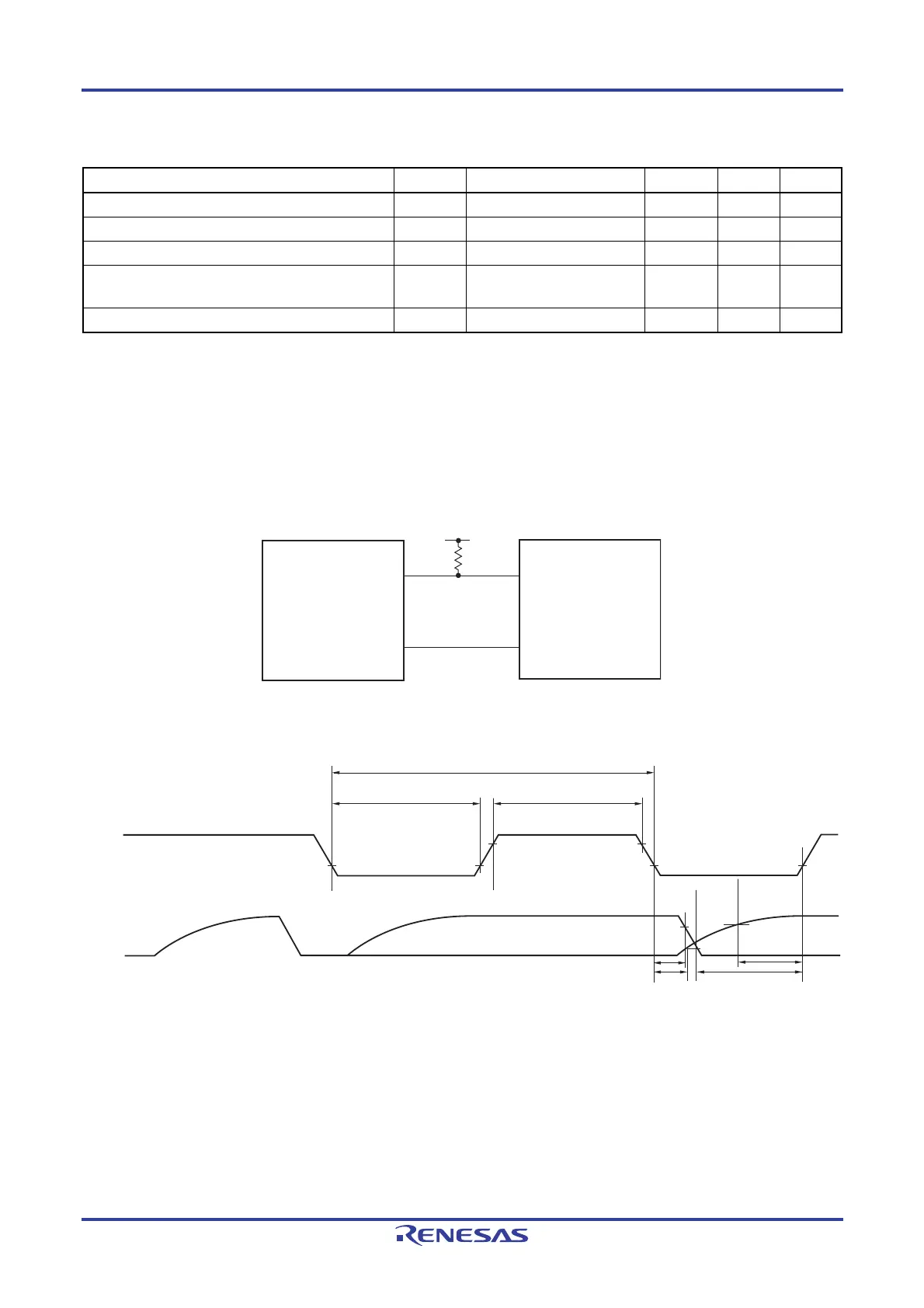
Simplified I
2
C mode connection diagram
SDA00
SCL00
SDA
SCL
V
b
R
b
User's device
RL78 microcontroller
Simplified I
2
C mode serial transfer timing
SDA00
t
LOW
t
HIGH
t
HD:DAT
SCL00
t
SU:DAT
1/f
SCL
Remarks 1. Rb [Ω]: Communication line (SDAr) pull-up resistance,
Cb [F]: Communication line (SCLr, SDAr) load capacitance
2. r: IIC number (r = 00)
3.
fMCK: Serial array unit operation clock frequency
(Operation clock to be set by the serial clock select register 0 (SPS0) and the CKS0n bit of the serial
mode register 0nH (SMR0nH). n: Channel number (n = 0))

 Loading...


