RL78/G10 APPENDIX A REVISION HISTORY
R01UH0384EJ0311 Rev. 3.11 610
Dec 22, 2016
(2/9)
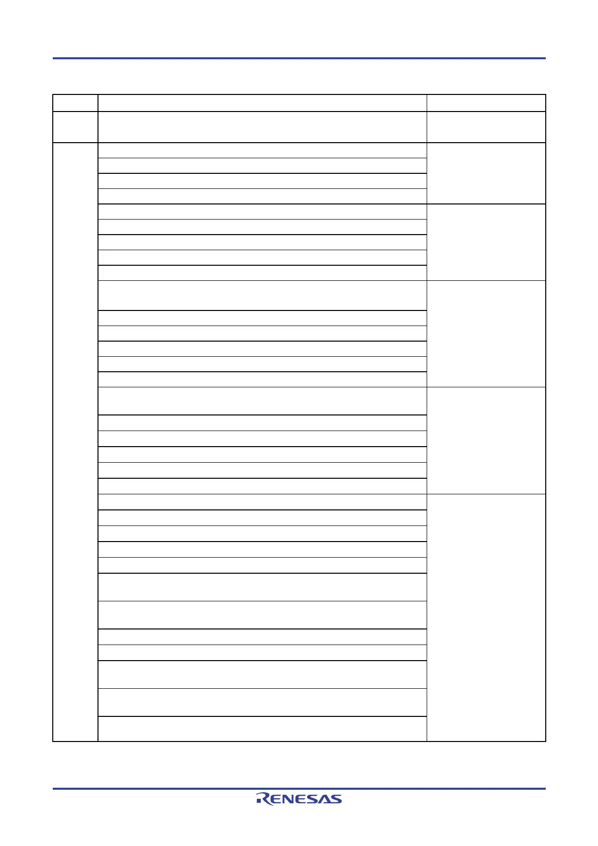
Edition
Description Chapter
Rev.3.00
Addition of industrial application in 25.2 16-pin products and modification of package
drawing
CHAPTER 25 PACKAGE
DRAWINGS
Rev.2.00
Modification of descriptions in 1.1 Features
CHAPTER 1
OUTLINE
Modification of description in 1.2 List of Part Numbers
Modification of remark 2 in 1.3.1 10-pin products and 1.3.2 16-pin products
Addition of description of R5F10Y17ASP in 1.6 Outline of Functions
Modification of description in 2.1.1 10-pin products
CHAPTER 2
PIN FUNCTIONS
Modification of description in 2.1.2 16-pin products
Modification of description in 2.2.1 Functions for each product
Modification of description in 2.2.2 Description of functions
Addition of Figure 2-8 in 2.4 Block Diagrams of Pins
Modification of description in Figure 3-1 Memory Map for the R5F10Y14ASP and
R5F10Y44ASP to Figure 3-3 Memory Map for the R5F10Y17ASP and R5F10Y47ASP
CHAPTER 3
CPU ARCHITECTURE
Addition of R5F10Y17ASP in Table 3-1 Internal ROM Capacity
Addition of specification of 16-pin products in Table 3-2
Modification of figure in 3.1.2
Modification of description and addition of caution in 3.1.3 Internal data memory space
Addition of description of R5F10Y17ASP in Table 3-3 Internal RAM Capacity
Modification of description in Figure 3-4 Correspondence Between Data Memory and
Addressing
CHAPTER 3
CPU ARCHITECTURE
Modification of description in (3) Stack pointer (SP) and addition of caution 2
Addition of registers related to the comparator in Table 3-4 SFR List
Modification of note 2 in Table 3-4 SFR List
Addition of A/D test register in Table 3-5 Extended SFR (2nd SFR) List
Addition of note 2 in Table 3-5 Extended SFR (2nd SFR) List
Modification of description in 4.2.1 Port 0 to 4.2.4 Port 13
CHAPTER 4
PORT FUNCTIONS
Modification of caution in 4.3 Registers Controlling Port Function
Addition of caution in Figure 4-1 Format of Port Mode Registers 0, 4 (PM0, PM4)
Modification of note in 4.3.2 Port registers 0, 4, 12, 13 (P0, P4, P12, P13)
Addition of caution in Figure 4-2 Format of Port Registers 0, 4, 12, 13 (P0, P4, P12, P13)
Modification of description in 4.3.3 Pull-up resistor option registers 0, 4, 12 (PU0, PU4,
PU12)
Modification of note and addition of caution in Figure 4-3 Format of Pull-up Resistor
Option Registers 0, 4, 12 (PU0, PU4, PU12)
Addition of caution in 4.3.4 Port output mode register 0 (POM0)
Addition of caution in Figure 4-4 Format of Port Output Mode Register 0 (POM0)
Modification of caution 1 and addition of caution 2 in Figure 4-5 Format of Port Mode
Control Register 0 (PMC0)
Modification of description and addition of caution 2 in Figure 4-6. Format of Peripheral
I/O Redirection Register (PIOR)
Modification of description in 4.6.2 Notes on specifying the pin settings

 Loading...


