RL78/G10 APPENDIX A REVISION HISTORY
R01UH0384EJ0311 Rev. 3.11 611
Dec 22, 2016
(3/9)
Edition
Description Chapter
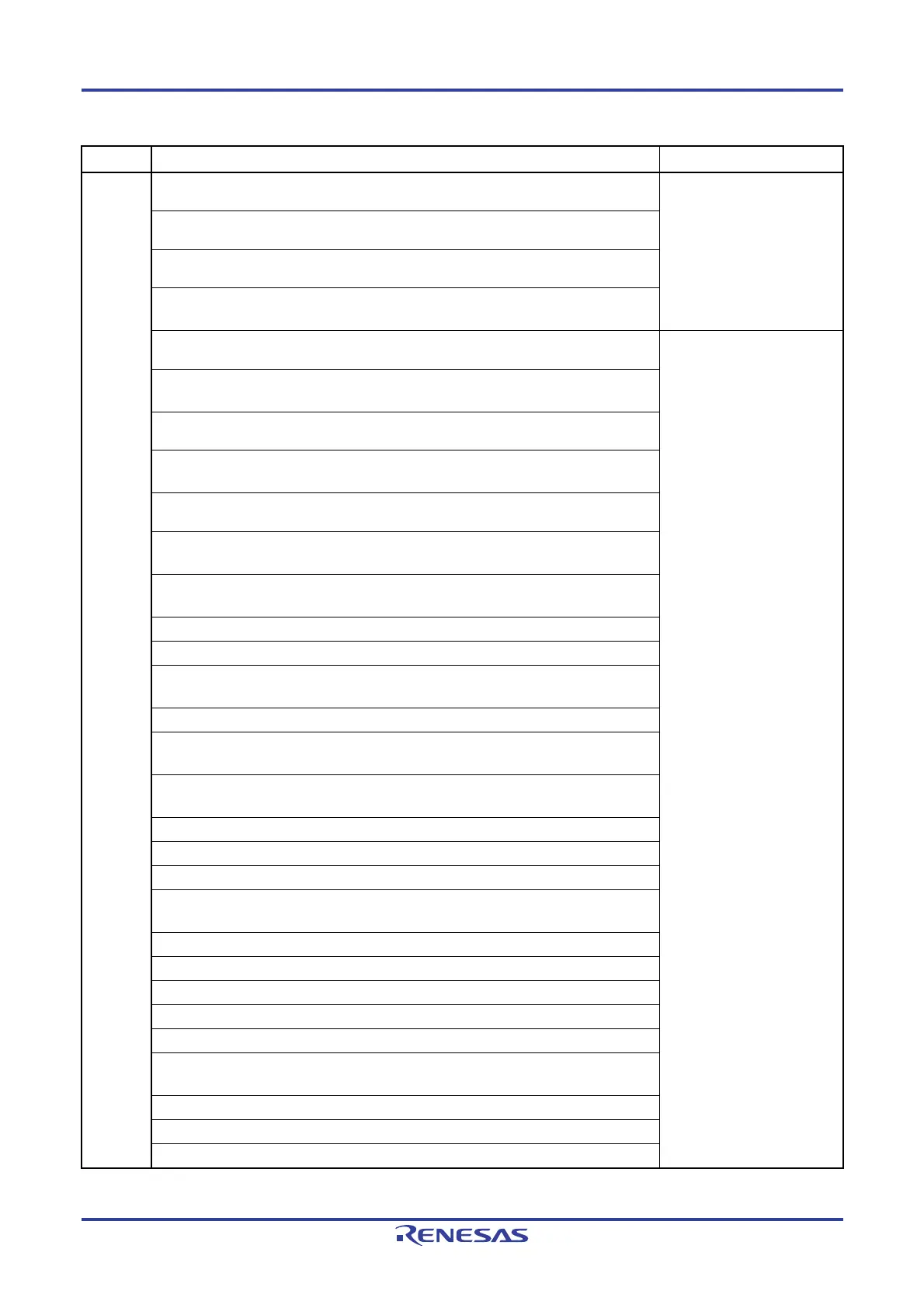
Rev.2.00
Modification of description in (1) Main system clock
CHAPTER 5
CLOCK GENERATOR
Addition of cautions 1 to 3 in Figure 5-3 Format of System Clock Control Register (CKC)
Addition of caution in Figure 5-7 Format of Peripheral Enable Register 0 (PER0)
Addition of specification in (2) CPU clock changing from high-speed system clock (B) to
high-speed on-chip oscillator clock (A)
Addition of description
CHAPTER 6
TIMER ARRAY UNIT
Addition of description in (2) Two-channel input with one-shot pulse output function (16-
pin products only)
Modification of Figure 6-1 Entire Configuration of Timer Array Unit
Block diagram of (b) Channels 1 and 3 was divided into (b) Channel 1 and (c) Channel 3
in Figure 6-2 Internal Block Diagram of Channel of Timer Array Unit
Modification of caution 2 in Figure 6-6 Format of Peripheral Enable Register 0 (PER0)
Modification of description and addition of caution in Figure 6-8 Format of Timer Mode
Register 0n (TMR0n) (2/3)
Modification of description in 6.3.5 Timer channel enable status register 0 (TE0, TEH0 (8-
bit mode))
Modification of description in 6.3.8 Timer output enable register 0 (TOE0)
Modification of description and remark in 6.3.11 Timer output mode register 0 (TOM0)
Modification of description and addition of caution in 6.3.12 Noise filter enable register 1
(NFEN1)
Addition of 6.3.13 Input switch control register (ISC)
Modification of description in 6.3.14 Registers controlling port functions of pins to be used
for timer I/O
Modification of description in 6.4.2 Basic rules of 8-bit timer operation function (only
channels 1 and 3)
Modification of description in 6.6.1 TO0n pin output circuit configuration
Addition of description in 6.7 Timer Input (TI0n) Control
Modification of description in 6.8.1 Operation as interval timer/square wave output
Modification of description in Figure 6-43 Procedure for Operating Interval
Timer/Outputting Square Wave
Modification of description in 6.8.2 Operation as external event counter
Modification of description in Figure 6-47 Procedure for Operating External Event Counter
Modification of description in Figure 6-51 Procedure for Operating Frequency Divider
Modification of description in 6.8.4 Operation as input pulse interval measurement
Modification of description in Figure 6-55 Procedure for Measuring Input Pulse Interval
Modification of description in Figure 6-59 Procedure for Measuring Input Signal High-
/Low-Level Width
Addition of caution in 6.8.6 Operation as delay counter
Modification of description in Figure 6-63 Procedure for Operating Delay Counter
Addition of caution in 6.9.1 Operation as one-shot pulse output

 Loading...


