RF: Connection Control CMU
1100.4903.12 4.66 E-10
Besides, the tab controls the Wideband power meter and displays the result.
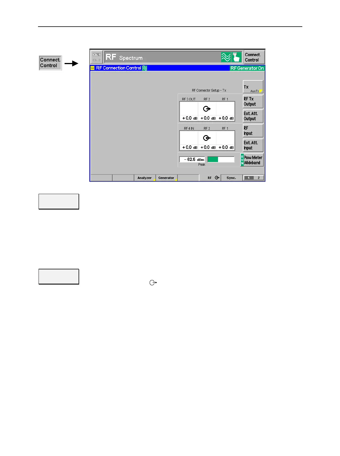
Fig. 4-31 Connection Control – RF connectors
Tx
Aux Tx
Tx / Aux Tx toggles between the primary RF signal Tx and the additional signal Aux
Tx, to be routed to one of the RF output connectors of the instrument.
The two RF signals are independent from each other. It is possible to route the
signals to different RF output connectors or superimpose them at the same con-
nector. If Aux Tx is selected, RF Tx Output changes to RF Aux Tx Output, and the
input softkeys are hidden.
Remote control
OUTPut[:STATe] RF1 | RF2 | RF3
RF Tx
Output
The RF Tx Output softkey defines which of the three connectors RF 1, RF 2 and
RF 3 OUT is to be used as RF output connector for the Tx signal. The selected RF
output is indicated by a
symbol.
If the additional RF signal Aux Tx is selected (see above), the softkey is labeled
RF Aux Tx Output and selects the output connector for AuxTx.
Note: Input and output connectors can be combined at will. The bidirectional
connectors RF 1 and RF 2 can be selected as RF inputs and outputs
at the same time.
The LEDs on the front panel are only „on“ (light) if the output level is
switched on.
Remote control
OUTPut[:TX][:STATe] RF1 | RF2 | RF3
OUTPut:AUXTx[:STATe] RF1 | RF2

 Loading...


