Hardware Interfaces CMU
1100.4903.12 8.2 E-8
Hardware Interfaces
GPIB Bus Interface
The standard instrument is equipped with an GPIB bus (IEC/IEEE-bus) connection. The interface
connector labeled IEEE 488 / IEC 625 is located on the rear panel of the instrument. A controller for
remote control can be connected via the GPIB bus interface using a shielded cable.
Characteristics of the Interface
!
8-bit parallel data transfer
! Bidirectional data transfer
! Three-line handshake
! High data transfer rate of max. 1 MByte/s
! Up to 15 devices can be connected
! Maximum length of the connecting cables 15 m. The length of a single connecting cable should not
exceed 2 m, if many devices are used, it should not exceed 1 m.
! Wired OR if several instruments are connected in parallel
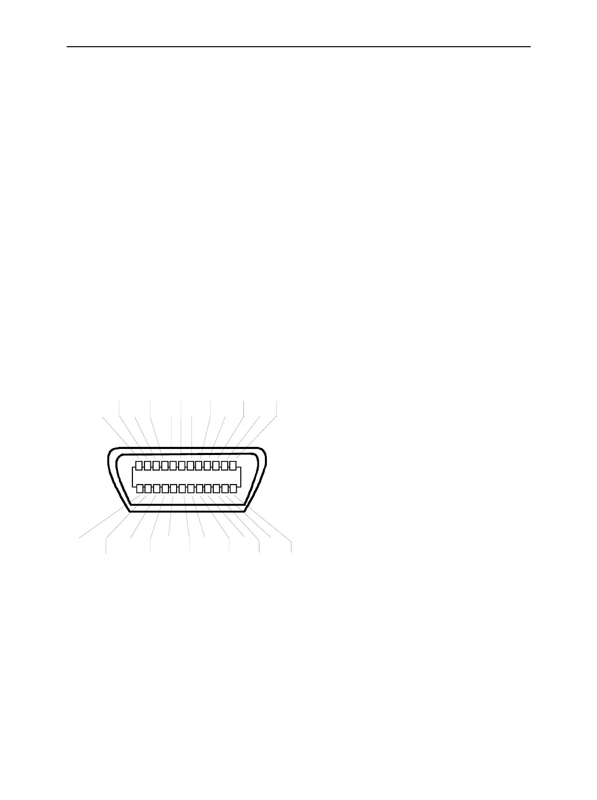
12
1
13
24
GND SRQ NDAC DAV D3 D1
GND(24) GND(22) GND(20) GND(18) D7 D5
GND(23) GND(21) GND(19) REN D6 D4
ATN IFC NRFD EOI D2 D0
Fig. 8-1 Pin Assigment of the GPIB bus interface
Bus Lines
1. Data bus with 8 lines D0 to D7
The transmission is bit-parallel and byte-serial in the ASCII/ISO code. D0 is the least significant
bit, D7 the most significant bit.

 Loading...


