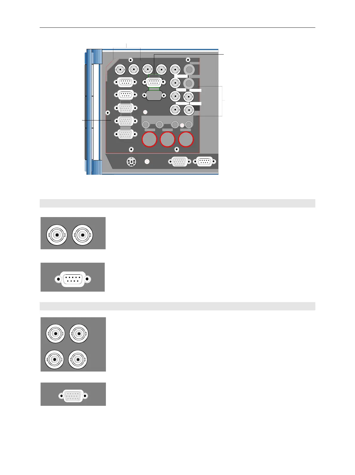
CMU Rear View
1100.4903.12 1.9 E-10
KEYBOARD
MONITOR
COM 1
AUX
SERVICE
IF 3 RX CH1
Input and output for Abis interface (CMU 300 only)
REF OUT 1 REF OUT 2
REF IN
REF OUT 1REF IN
IF interface
(CMU 200 only)
AUX4
I/Q CH1
IF3 RX CH1 IN
IF3 RX CH1 IN IF3 RX CH1 IN
IF3 RX CH1 IN
ABIS TX
ABIS RX
ABIS
I/Q interface
(CMU 200 only)
Balanced Abis
interface
(CMU 300 only)
Fig. 1-9 CMU rear view – Abis and I/Q-IF inputs and outputs
Abis connectors (CMU300 with option CMU-B71)
ABIS TX ABIS RX
Two 75 Ω BNC connectors for option CMU-B71, Abis
Interface Unit for CMU (for CMU300 only):
ABIS TX For future extensions
ABIS RX Input for PCM signals from a BTS under
test to be applied to the CMU's Abis
interface
!
Operating manual
CMU-K30/-K31/-
K32/-K33/-K34
ABIS
9-contact SUB-D connector with alternative
120 Ω balanced input for Abis interface .
!
Chapter 8,
"Hardware
Connectors"
I/Q-IF Interface (CMU200 with option CMU-B17)
IF3 RX CH1 IN
IF3 RX CH1 OUT
IF3 TX CH1 IN
IF3 TX CH1 OUT
Four 50 Ω BNC connectors for option CMU-B17, I/Q and
IF Interface (for CMU200 only):
IF3 RX CH1 IN RX path, IF IN
IF3 RX CH1 OUT RX path, IF OUT
IF3 TX CH1 IN TX path, IF IN
IF3 TX CH1 OUT TX path, IF OUT
!
Chapter 4,
"Hardware
Connectors"
Chapter 8,
"Hardware
Connectors"
I/Q CH1
15-contact SUB-D connector for input and output of I/Q
signals (option CMU-B17, I/Q and IF Interface, for
CMU200 only)
!
Chapter 8,
"Hardware
Connectors"
Note: The CMU is delivered with different rear panel designs, however, the names of the
connectors are unambiguous and used irrespective of the design.

 Loading...


