Audio Generator and Analyzer (Option CMU-B41) CMU
1100.4903.12 4.94 E-10
signal. This level is evenly distributed among all enabled test
tones. This means that the level of each enabled test tone is set
to Total Level / n where n is the number of enabled test tones (n
= 1 to 20). If a test tone is disabled, the total level is maintained
and the share of the remaining test tones in the total level in-
creases.
Remote control
CONFigure:MULTitone:AFxChannel:TDEFinition:MODE (x = 1,2)
SEParate | TLEVel
Tone Definitions
The Tone Definitions table assigns an audio Frequency (in Hz) and Level (RMS
voltage in mV) to each of the 20 test tones.
The frequencies must be multiples of 1 Hz. It is possible, however, to define several
tones at the same frequency, or to number the tones in arbitrary order: The x-axis
is scaled by the number of the test tones, not by their frequency. The RMS volt-
ages of different tones may coincide and can vary within the range quoted in the
remote control command description in chapter 6 of this manual. The sum of all test
tones must not exceed the maximum level of the AF generator quoted in the data
sheet.
Note: The voltages of all test tones enabled can be set manually or auto-
matically, depending on the setting of the Level Selection parameter
described above.
The AF Gen. checkbox switches the tone in the audio signal and the corresponding
bar in the test diagram on (if checked) or off.
Remote control
CONFigure:MULTitone:AFxChannel:TDEFinition
<Freq_1>,<Level_1>,<Enable_1>,...
CONFigure:MULTitone:AFxChannel:TDEFinition:TONE<nr>
<Freq>,<Level>,<Enable>,... (x = 1,2)
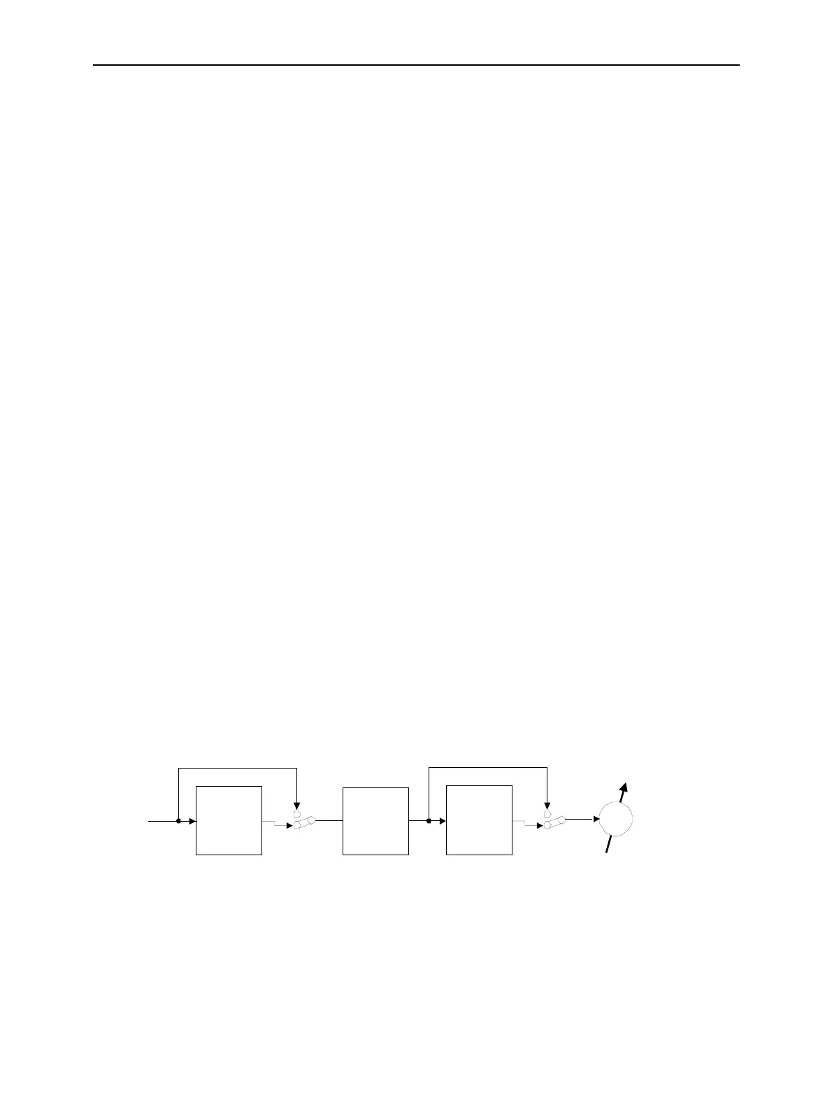
Input Path Configuration (Multitone Configuration – Filter)
The Filter tab configures the receive path of the CMU for the Multitone measurement (see Fig. 4-44
below). All parameters can be set independently for the two AF channels 1 and 2.
Audio Multitone
Measurement
Weighting
filter
Block
DC current
DC Coupling
Band pass
AC Coupling
Amplified
signal
from input
AF IN
Band pass selection
depending on DC/AC coupling
at the input
Fig. 4-44 Signal path for Multitone measurements

 Loading...


