CMU I/Q and IF Interface (Option CMU-B17)
1100.4903.12 4.97 E-10
I/Q and IF Interface (Option CMU-B17)
Option CMU-B17 provides separate access to the I/Q and IF signals in the CMU200 receiver (RX) and
transmitter (TX) paths. The functionality is applicable in conjunction with the RF function group (see
section I/Q-IF Interface (Connection Control – I/Q-IF) REFFORMATVERBINDENon p. 4.74 ff.) and with
a wide range of network options in Signalling as well as in Non Signalling test modes (see separate
manuals for network options). The insertion of option CMU-B17 in bypass mode does not cause any
influence on signals; i.e. the additional insertion loss caused by option CMU-B17 will be corrected dur-
ing the mandatory calibration procedure after installation.
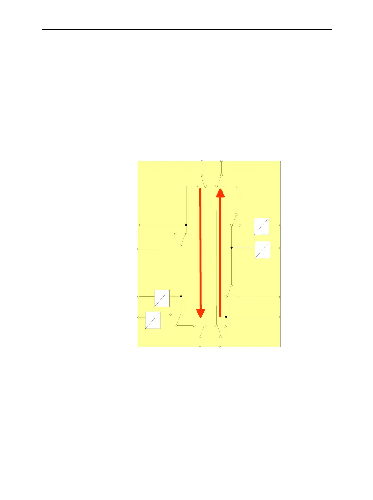
Block diagram
The diagram below shows the possible signal paths and the input and output con-
nectors related to option CMU-B17. The position of the connectors on the rear
panel is shown in Chapter 1; for the technical specifications and the pin assignment
refer to Chapter 8.
IQ
IF
IQ
IF
to RF Unit
to Di
ital Unit
IQ
IF
IQ OUT
IQ OUT
IQ
IF
IQ IN
IQ IN
IF IN
IF IN
IF OUT
IF OUT
Bypass
RX path
TX path
CMU-B17
IF
IF
(rear panel
I/Q CH1)
(rear panel
I/Q CH1)
(rear panel
IF3 TX CH1 IN)
(rear panel
IF3 TX CH1 OUT)
(rear panel
IF3 RX CH1 IN)
(rear panel
IF3 RX CH1 OUT)
Fig. 4-46 I/Q-IF Interface
I/Q-IF Test Scenarios
A short overview of test scenarios with the necessary RX and TX path settings is given in Table 4-1 on
p. 4.75. The following examples illustrate the functionality in more detail.
The list of scenarios is not necessarily complete: Depending on the application, it is possible to define
customized, User defined test scenarios.

 Loading...


