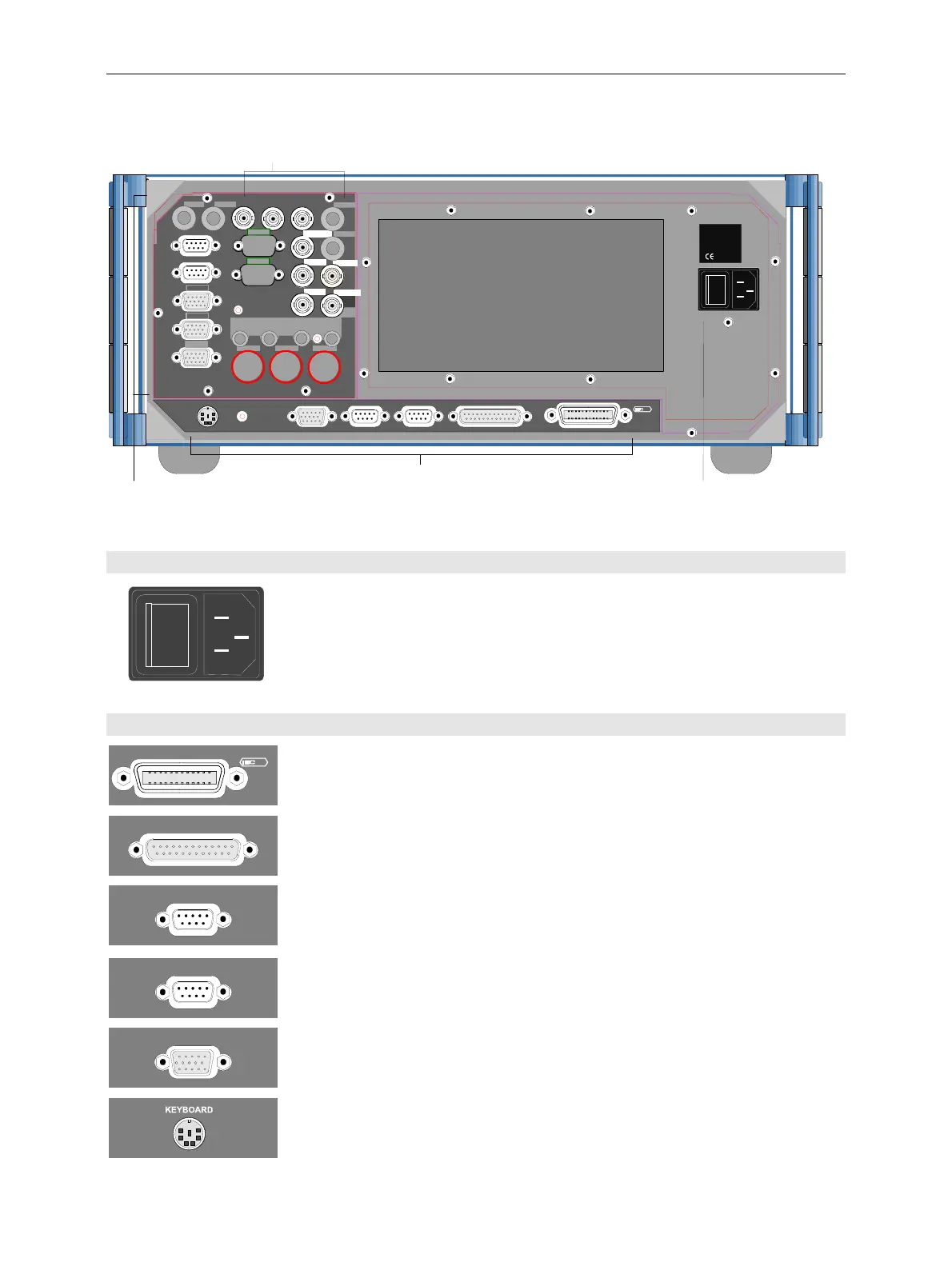
CMU Rear View
1100.4903.12 1.7 E-10
Rear View
KEYBOARD
MONITOR COM 1 COM 2
IEEE 488
625
REF IN
REF OUT 1 REF OUT 2
AUX
LPT
I
0
SERVICE
IF 3 RX CH1
Interfaces for remote control
and peripheral equipment
Mains connector with switch
Signal inputs and outputs
o
I
100-240VAC
3,1-1,3 A
50-400 Hz
ync
ron
zat
on
nputs an
outputs,
nter
ace
w
t
opt
on
-
AUX4
I/Q CH1
IF3 RX CH1 IN
IF3 RX CH1 OUT
IF3 TX CH1 IN
IF3 TX CH1 OUT
Fig. 1-7 CMU rear view
Mains switch
o
I
Mains power switch
Mains connector
!
!
Chapter 1, "Switching on the Instrument,
Startup test"
Chapter 1, "Connecting the instrument to the
AC supply”
Interfaces
IEEE 488
625
LPT
COM 1
GPIB-bus connector
(IEEE 488 / IEC 625),
Parallel interface: 25-contact
printer connector, Centronics-
compatible
Connector for serial interface 1: 9-
contact Sub-D connector
!
!
!
Chapter 8, "Hardware Interfaces "
Chapt. 1, "Connecting an Output Device"
Chapter 8, "Hardware Interfaces”
Chapter 8, "Hardware Interfaces”
COM2
MONI TOR
Connector for serial interface 2: 9-
contact Sub-D connector
Connector for an external VGA
monitor: 15-contact Sub-D
connector
Connector for external keyboard
(PS/2), 6-contact Mini DIN
connector
!
!
!
Chapter 8, "Hardware Interfaces”
Chapter 1, "Connecting a Monitor"
Chapter 8, "Hardware Interfaces”
Chapter 1, "Connecting an External Keyboard"
Chapter. 8, "Hardware Interfaces”

 Loading...


