Status Reporting System CMU
1100.4903.12 5.16 E-8
Status Reporting System
The status reporting system (cf. Fig. 5-5) stores all information on the present operating state of the
instrument, and on errors which have occurred. This information is stored in the status registers and in
the error queue. The status registers and the error queue can be queried via GPIB bus.
The information is of a hierarchical structure. The register status byte (STB) defined in IEEE 488.2 and
its associated mask register service request enable (SRE) form the uppermost level. The STB receives
its information from the standard event status register (ESR) which is also defined in IEEE 488.2 with
the associated mask register standard event status enable (ESE) and registers STATus:OPERation
and STATus:QUEStionable which are defined by SCPI and contain detailed information on the instru-
ment.
The IST flag ("I
ndividual STatus") and the parallel poll enable register (PPE) allocated to it are also part
of the status reporting system. The IST flag, like the SRQ, combines the entire instrument status in a
single bit. The PPE fulfills an analog function for the IST flag as the SRE for the service request.
The output buffer contains the messages the instrument returns to the controller. It is not part of the
status reporting system but determines the value of the MAV bit in the STB and thus is represented in
Fig. 5-5.
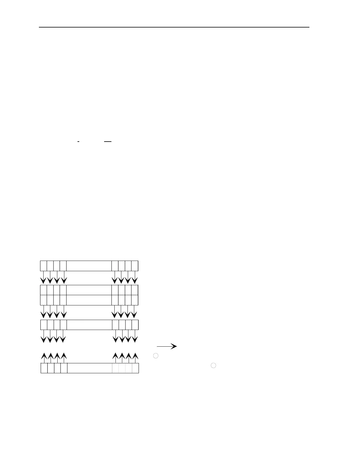
Structure of an SCPI Status Register
Each standard SCPI register consists of 5 parts which each have a width of 16 bits and have different
functions (cf. Fig. 5-4). The individual bits are independent of each other, i.e. each hardware status is
assigned a bit number which is valid for all five parts. Bit 15 (the most significant bit) is set to zero for all
parts. Thus the contents of the register parts can be processed by the controller as positive integer.
15 14 13 12 PTRansition part 3 2 1 0
15 14 13 12 EVENt part 3 2 1 0
15 14 13 12 ENABle part 3 2 1 0
& & & & & & & & & & & & & & & &
to higher-order register
Sum bit
& = logical AN
= logical OR
of all bits
+
+
15 14 13 12 NTRansition part 3 2 1 0
15 14 13 12 CONDition part 3 2 1 0
Fig. 5-4 The status register model

 Loading...


