CMU Instrument Model and Command Processing
1100.4903.12 5.13 E-8
Instrument Model and Command Processing
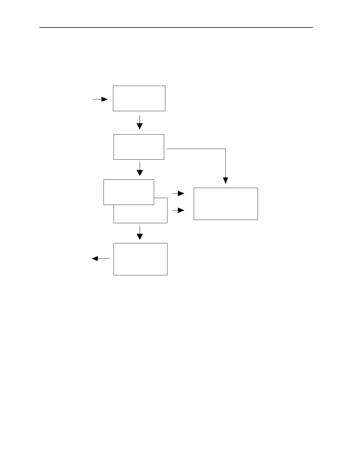
The block diagram in figure Fig. 5-3 shows how GPIB bus commands are serviced in the instrument.
The individual components work independently and simultaneously. They communicate with each other
by means of so-called "messages".
GPIB bus
Input unit with
input buffer
Command
recognition
Data set
Instrument
hardware
GPIB bus
Output unit with
output buffer
Status reporting
system
Fig. 5-3 Instrument model in the case of remote control via GPIB bus
Input Unit
The input unit receives commands character by character from the GPIB bus and collects them in the
input buffer. The input unit sends a message to the command recognition as soon as the input buffer is
full or as soon as it receives a delimiter, <PROGRAM MESSAGE TERMINATOR>, as defined in IEEE
488.2, or the interface message DCL.
If the input buffer is full, the GPIB bus traffic is stopped and the data received up to then are processed.
Subsequently the GPIB bus traffic is continued. If, however, the buffer is not yet full when receiving the
delimiter, the input unit can already receive the next command during command recognition and execu-
tion. The receipt of a DCL clears the input buffer and immediately initiates a message to the command
recognition.

 Loading...


