CMU Audio Generator and Analyzer (Option CMU-B41)
1100.4903.12 4.83 E-10
Level
Level defines the generator level in mV. The meaning of the entered level depends
on the generator signal type (see Signal below):
If the generated signal is an AC signal, Level denotes the effective (RMS averaged)
voltage.
If the generated signal is an DC signal, Level denotes the constant DC voltage.
Remote control
SOURce:AFGenerator:<Applic>:LEVel <Level>
Signal
Signal qualifies whether the generated audio signal is a DC or an AC signal.
Remote control
SOURce:AFGenerator:<Applic>:SMODe DC | AC
Frequency
Frequency sets the frequency of the generated AF audio signal in Hz. The hotkey
is disabled if the generated signal is a DC signal.
Remote control
SOURce:AFGenerator:<Applic>:FREQuency <Frequency>
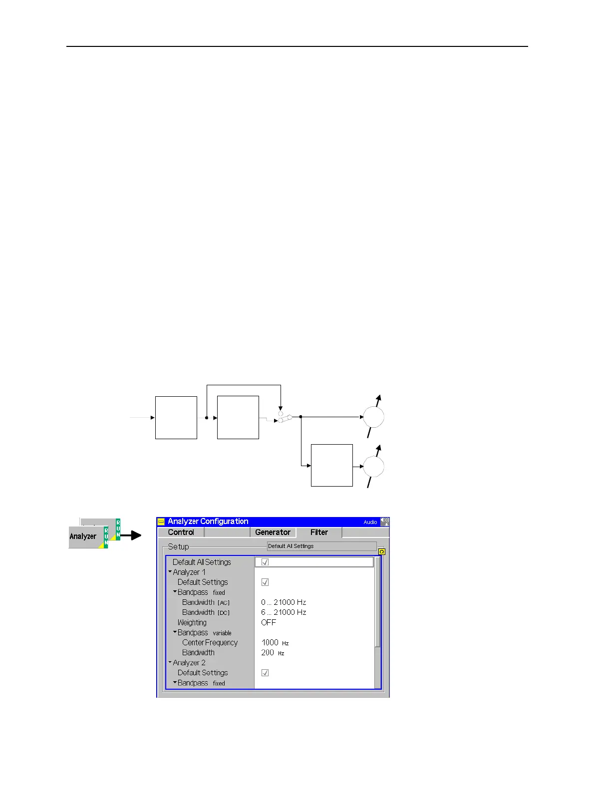
Input Path Configuration (Analyzer Configuration – Filter)
The Filter tab configures the different filter stages for the AF analyzer. The input path for measuring the
AC component of the AF signal is as shown below:
Weighting
filter
Variable
band pass
AC Voltage (Peak) 1
AC Voltage (RMS) 1
AC Voltage (Peak) 2 (remote control only
AC Voltage (RMS) 2 (remote control only)
Signal from AF IN
(AC or DC coupling)
Fixed
band pass
Fig. 4-37 AF analyzer input path configuration
Fig. 4-38 Analyzer Configuration – Filter

 Loading...


