CMU RF Measurements
1100.4903.12 6.39 E-10
Subsystem INPut, OUTPut, CORRection:LOSS ( /Ext. Att.)
The subsystem for input and output contains the commands for configuration of the input and output
connectors. The subsystem corresponds to the tab RF in the popup menu Connect. Control.
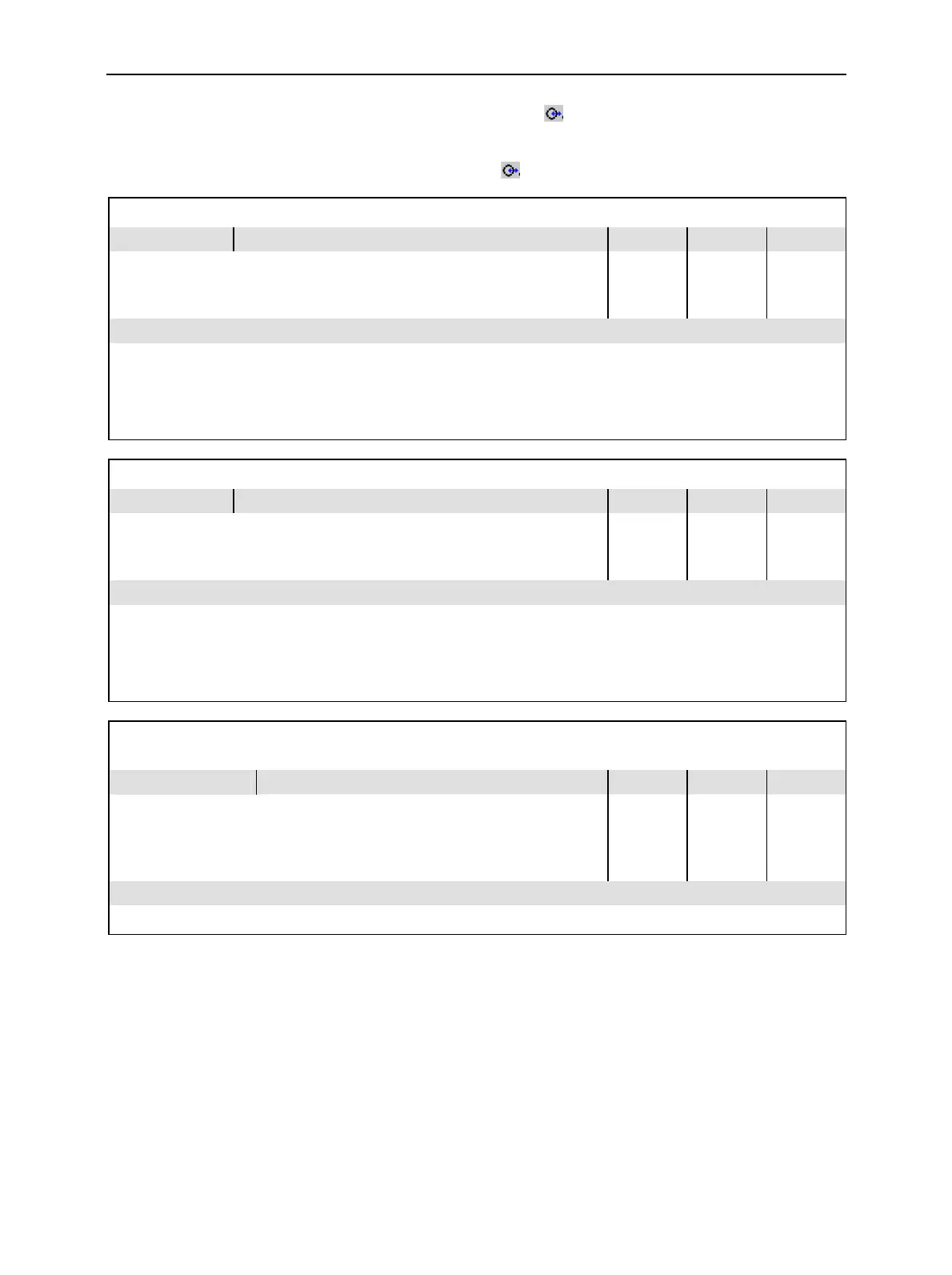
INPut[:STATe] <State> RF Input
<State>
Parameter description Def. value Default unit FW vers.
RF1
RF2
RF4
Connector RF1 used as input
Connector RF2 used as input
Connector RF4 IN used as input
RF2 – V1.15
Command description
This command determines the connector to be used for incoming RF signals.
The bidirectional connectors RF 1 and RF 2 can be used both as input and output connectors in the same meas-
urement (see OUTPut[:STATe]). Only one input and one output may be active at a time, which is why the cur-
rently active one is automatically deactivated on switchover.
OUTPut[:TX][:STATe] <State> RF Output
<State>
Parameter description Def. value Default unit FW vers.
RF1
RF2
RF3
Connector RF1 used as output
Connector RF2 used as output
Connector RF3 OUT used as output
RF2 – V1.15
Command description
This command determines the connector to be used for outgoing RF signals.
The bidirectional connectors RF 1 and RF 2 can be used both as input and output connectors in the same meas-
urement. Only one input and one output may be active at a time, which is why the currently active one is auto-
matically deactivated.
[SENSe:]CORRection:LOSS:INPut<nr>[:MAGNitude] <Absorption>
SOURce:CORRection:LOSS:INPut<nr>[:MAGNitude] <Absorption> Ext. Att. Input
<Absorption>
Parameter description Def. value Default unit FW vers.
–50 dB to +50 dB
–90 dB to +90 dB
Value for external attenuation at Input <nr>, where
<nr> = 1,2
Value for external attenuation at Input <nr>, where
<nr> = 4
0.0
0.0
dB
dB
V1.15
Command description
This commands assigns an external attenuation value to the inputs of the instrument.

 Loading...


