CMU Hardware Interfaces
1100.4903.12 8.13 E-8
AF Connector SPEECH (Optional)
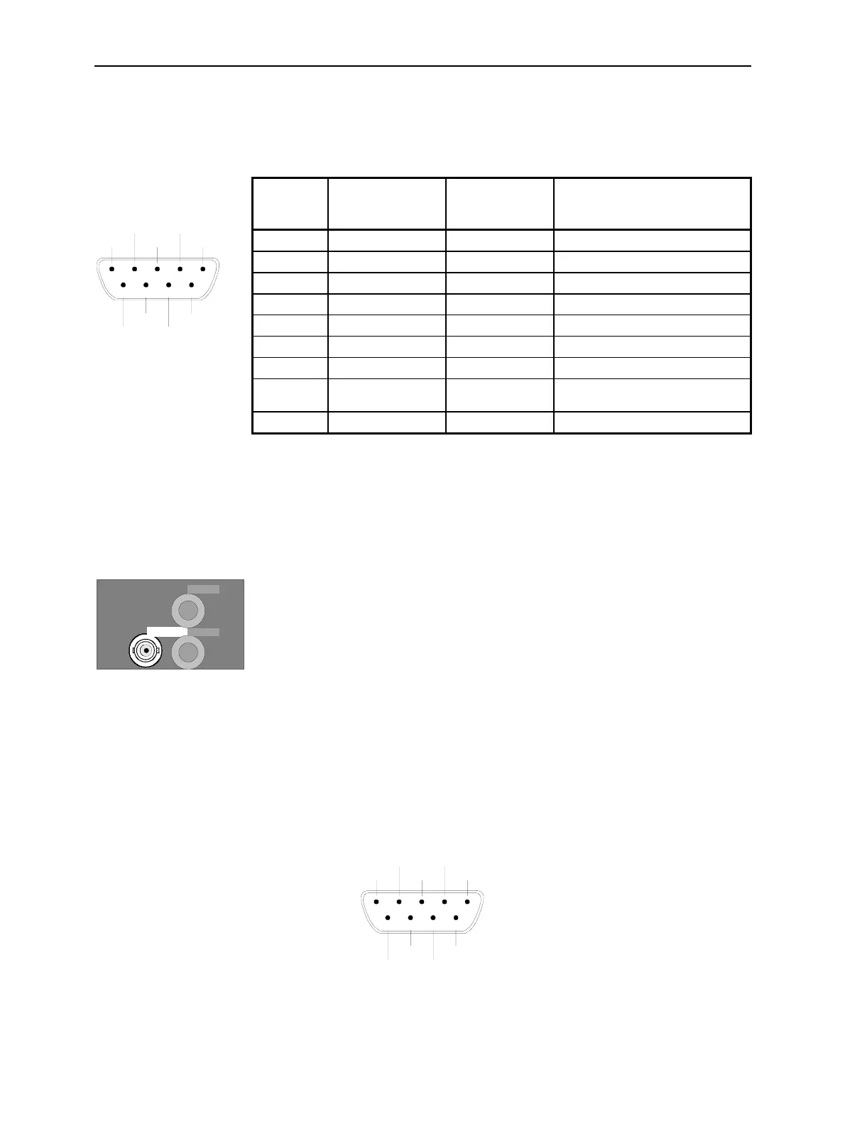
The 9-pin Sub-D female connector SPEECH on the front panel of the instrument can be used for
connecting a handset to the signalling unit.
12345
67
89
GND
GND
KEYB
GND
SPEECH
LH2IN LH1OUT
LH1IN
LH2OUT
GND
Fig. 8-10 AF connector SPEECH
IF Signal
One BNC connector providing an IF signal is located on the rear panel of the CMU.
IF 3 RX CH1
IF3 RX CH1 connector (BNC socket), provides an IF signal from the RXTX
board 1 for monitoring purposes.
Fig. 8-11 IF signal output
Service and Auxiliary Connectors
A 9-pin Sub-D female connector SERVICE for the modules RXTX Boards is located on the rear panel.
This connector is intended for internal tests only and must not be used as a signal input or output.
12345
67
89
GND
GND
RES
GND
SERVICE
TXD1
RXD1
RXD2
TXD2
RES
Fig. 8-12 SERVICE connector
Pin No. Signal Input (I) /
Output (O) /
Bidirectional (B)
Description
1 GND B
2 LH1HAND SETIN I AF signals to signalling unit 1
3 LH1HAND SETOUT O AF signals from signalling unit 1
4 GND B
5 LH2HAND SETIN I Signals to signalling unit 2
6 LH2HAND SETOUT O Signals from signalling unit 2
7 GND B
8 +5VKEYB O Power supply +5.2 V,
max. 100 mA
9 GND B

 Loading...


