CMU Hardware Interfaces
1100.4903.12 8.9 E-8
Hardware handshake
In case of a hardware handshake, the instrument signals that it is ready for reception via line DTR and
RTS. A logic '0' means "ready" and a '1' means "not ready". The RTS line is always active (logical '0'),
provided that the serial interface is switched on. The DTR line controls whether the analyzer is ready for
reception or not.
The CTS or DSR lines (see signal lines) tell the instrument whether the remote station is ready for
reception or not. A logical '0' on both lines switches on data transmission, a logical '1' on both lines
stops data transmission of the generator. The TxD line is used for data transfer.
1
2
3
4
5
6
7
8
9
DSUB connector, 9-pin / female
1
2
3
4
5
6
7
8
9
DCD
DSR
RxD
RTS
TxD
CTS
DTR
RI
GND
CMU Controller / PC
CMU Controller / PC
1
2
3
4
5
6
7
8
9
1
2
3
4
5
14
15
16
17
6
7
8
9
18
19
20
21
10
11
12
22
23
24
13
25
TxD
RxD
RTS
CTS
DSR
GND
DTR
DSUB connector, 9-pin / female
DSUB connector, 9 poles / female
DSUB connector, 25-pin / female
DCD
DSR
RxD
RTS
TxD
CTS
DTR
RI
GND
DCD
DSR
RxD
RTS
TxD
CTS
DTR
RI
GND
DCD
RI
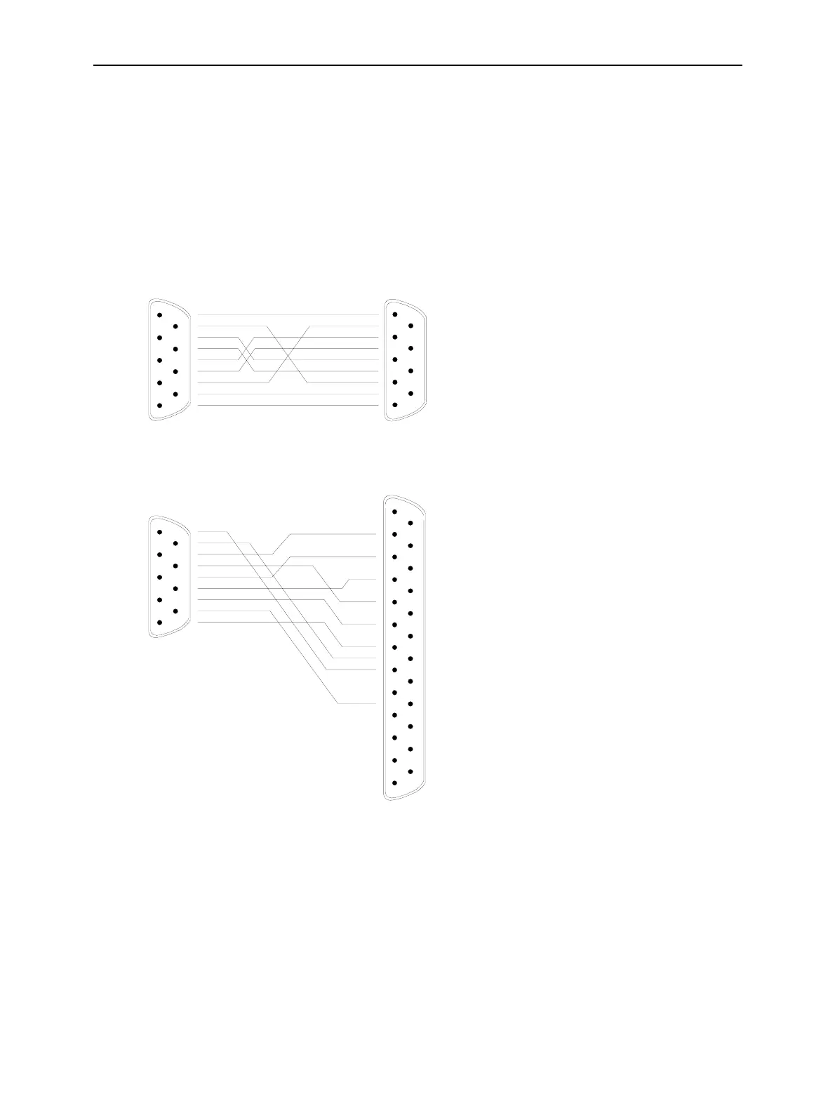
Connection between instrument
and controller (Null-modem cable)
The connection of the instrument to a
controller is made with a so-called
null-modem cable. Here, the data,
control and signalling lines must be
crossed. The wiring diagram on the
left applies to a controller with a 9-pin
or 25-pin configuration.
Fig. 8-4 Wiring of the data, control and message lines for hardware handshake

 Loading...


