CMU RF User Correction
1100.4903.12 1.27 E-10
RF User Correction
The purpose of the RF user correction is to compensate for an inevitable frequency and level-
dependent attenuation in the test setup (frequency and level response correction). Level correction
values are determined by means of a signal generator or power meter connected to the CMU’s input
and output ports and stored to a file, which is transferred to the CMU in order to modify its RF generator
level and to correct its RF analyzer results.
The correction values must be acquired independently for the input and output connectors of the
instrument.
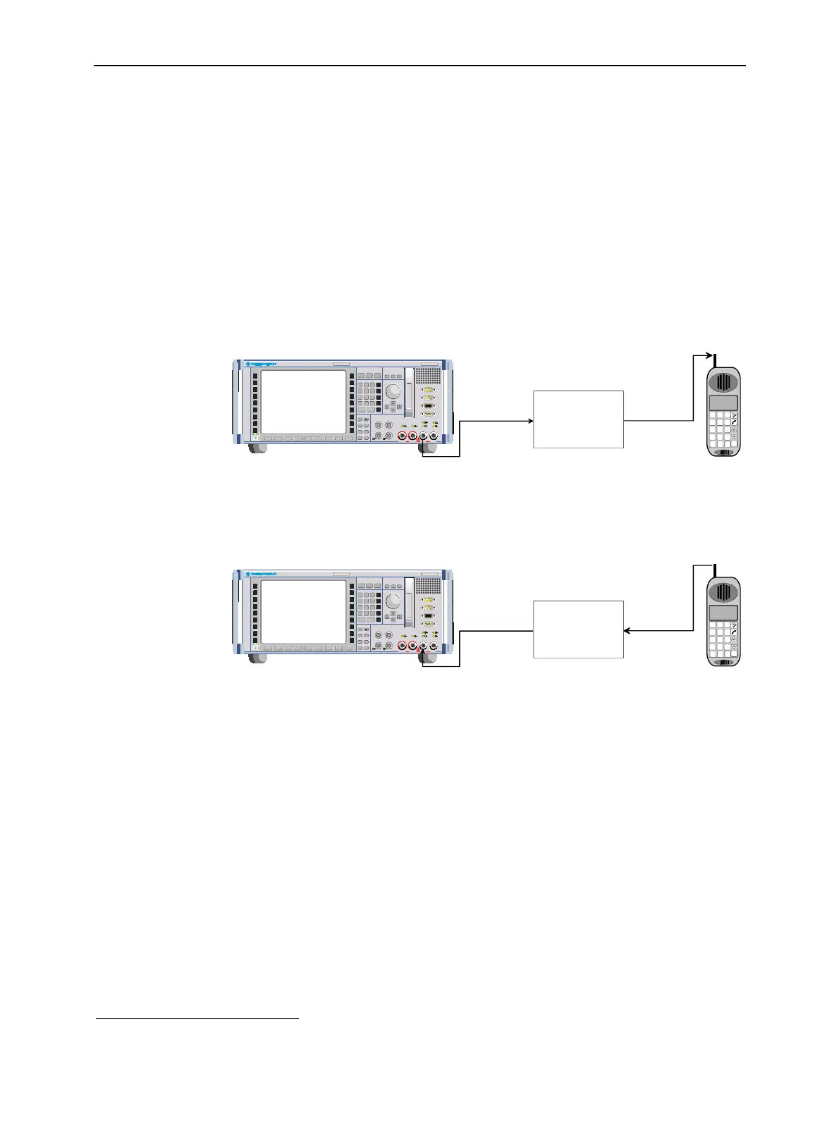
Output level
correction
The correction values for output signals (connectors RF1, RF2 or RF3 OUT)
modify the RF generator level so that the actual RF signal power at the input of
the DUT is equal to the nominal RF generator level.
Attenuation (P
nom
, f)
= x dB
(P
nom
+ x) dBm
P
nom
dBm
0
123
456
789
.
-
ON / OFF ENTER
1100.00 08.02
VARIATIONDATA
FUNCTION SYSTEM
CONTROL
DATA
CTRL
MENU
SELECT
HEL P SETUP
mark
symb
E
F
BM/µ
µV
W
C
dBµV
k/m
G/n
A
mV
D
1
dB
dBm
UNIT . . .
EXP/CMP CONT/HALT
RF4 IN
UNIVERSAL RADIO COMMUNICATION TE STER CMU 200
.
ESCAPE
*
abc def ghi
jkl mno pqr
stu
vwx yz
_ µ
AF IN AF OUT
VOL
DEL
AUTO
INF O RESET
PRINT
*
#
Ω
AUX 1 AUX 2
SPEECH
AUX 3
DATA 2
13 dBm
MAX
2 W
MAX
50 W
MAX
13 dBm
MAX
RF 3 OUT
RF 2 RF 1
DATA 1
INS
CLR
CMU
RF level: P
nom
dBm
RF Frequency: f
f
Correction(P
nom
, f) = x dB
x
2
DEF
3
GHI
1
ABC
564
8
ÜVW
7
STU
.
-
0
9
XYZ
SCRC L M
Input level
correction
The correction values for input signals (connectors RF1, RF2 or RF4 IN) modify
the measured analyzer level so that the result for the RF signal power is equal to
the power transmitted by the DUT.
Attenuation (P
nom
, f)
= x dB
(P
nom
- x) dBm
P
nom
dBm
0
123
456
789
.
-
ON / OFF ENTER
1100.00 08.02
VARIATIONDATA
FUNCTION SYSTEM
CONTROL
DATA
CTRL
MENU
SELECT
HEL P SETUP
mark
symb
E
F
BM/µ
µV
W
C
dBµV
k/m
G/n
A
mV
D
1
dB
dBm
UNIT . . .
EXP/CMP CONT/HALT
RF4 IN
UNIVERSAL RADIO COMMUNICATION TE STER CMU 200
.
ESCAPE
*
abc def ghi
jkl mno pqr
stu
vwx yz
_ µ
AF IN AF OUT
VOL
DEL
AUTO
INF O RESET
PRINT
*
#
Ω
AUX 1 AUX 2
SPEECH
AUX 3
DATA 2
13 dBm
MAX
2 W
MAX
50 W
MAX
13 dBm
MAX
RF 3 OUT
RF 2 RF 1
DATA 1
INS
CLR
CMU
RF Frequency: f
Correction(Pnom , f) = x dB
RF level (meas.): P
nom
dBm
x
2
DEF
3
GHI
1
ABC
564
8
ÜVW
7
STU
.
-
0
9
XYZ
SCRC L M
Once the correction tables have been transferred to the instrument, the RF user correction is an
internal procedure. There are several advantages of using this internal correction method rather than
post-processing the CMU results by means of an external measurement program:
• The input level correction affects all acquired RF power results
3
including derived quantities (e.g.
the results of the limit check) without slowing down the speed of the measurements. Evaluating
derived quantities by means of an external program can be tedious. The RF user correction
ensures that all results, including the derived ones, are consistent.
• The user correction is included in all results displayed in the measurement menus.
• Correction data can be acquired individually for each instrument and stored to its internal hard disk.
If several testers are used in a production measurement system, the individual units are
independent from each other and interchangeable.
3
Exception: The wideband power, which is provided in the Analyzer/Generator menu of the RF function group and in many network test applications, is always uncorrected.

 Loading...


