Hardware Interfaces CMU
1100.4903.12 8.14 E-8
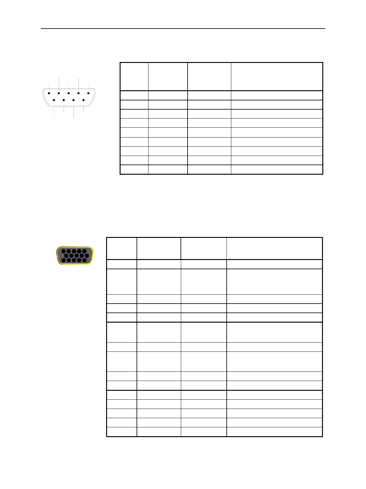
A 9-pin SUB-D female connector AUX on the rear panel provides a +5.2 V power supply. The pin
assignment is as follows:
12345
67
89
GND
GND
AUX
I2CSDA
+5VKEYB
I2CSCL
GND
RESERVE4
RES5
RESERVE5
Fig. 8-13 AUX connector
The 15-pin SUB-D female connector AUX 3 on the front panel is used as an input or output for status,
control, and trigger signals. These signals are applied to particular (in some function groups: selectable)
pins of the AUX 3 connector (refer to the corresponding menu).
The pin assignment of the AUX 3 connector is as follows:
AUX 3
1
6
11
5
10
15
Fig. 8-14 AUX 3 connector
Pin Signal Input (I) /
Output (O) /
Bidirectional
(B)
Description
1 GND B GND
2 +5VKEYB O Power supply +5.2 V, max. 100 mA
3 GND B GND
4 I2CSDA B For future extensions
5 I2CSCL
O
For future extensions
6 GND B GND
7 RESERVE4 B
8 RESERVE5 B
9 RESERVE6 B
1 GND B
2 TBUS1 O Timing output A
Test signal CH1
GSMxxx-MS Signalling: Frame trigger
(see GSMxxx-MS operating manual)
3 TBUS2 O Timing output B
4 TBUS3 O Timing output C
5 TBUS4 O Timing output D
6 TBUS5 I External trigger input
CMU300: External trigger signal for
wired synchronization
7 TBUS6 I External trigger B
8 TBUS7 I External trigger A
External trigger signal CH1 input for
Spectrum and Power measurements
9 GND B GND
10 GND B GND
11 GND B GND
12 GND B GND
13 GND B GND
14 GND B GND
15 GND B GND
Pin Signal Input (I) /
Output (A) /
Bidirectional (B)
Description

 Loading...


