Audio Generator and Analyzer (Option CMU-B41) CMU
1100.4903.12 4.82 E-10
Path
Coupling
Path Coupling sets the input path for measurement of the AC or AC and DC com-
ponent of the AF signal:
AC DC component of the measured AF signal (including a possible
DC offset of the input amplifier) blocked. This ensures accurate
measurement of the AC component. The DC component, how-
ever, can not be measured.
DC Measurement of the complete AF input signal (DC plus AC com-
ponents).
Note: The path coupling has an impact on the allowed filter settings; see
section Input Path Configuration (Analyzer Configuration – Filter) on p.
4.82 f.
Remote control
CONFigure:AFANalyzer:<Applic>:CONTrol:COUPling AC | DC
Distortion
Frequency
Distortion Frequency defines the reference frequency of the distortion measure-
ment. If the reference frequency is set to the fundamental frequency of the AF sig-
nal, the Distortion value corresponds to the Total Harmonic Distortion and Noise.
Remote control
CONFigure:AFANalyzer:<Applic>:CONTrol:DISTortion:FREQuency
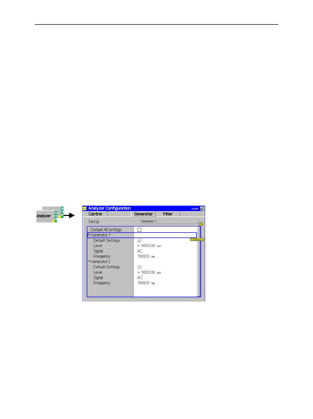
Generator Settings (Analyzer Configuration – Generator)
The Generator tab defines the properties of the generated AF signals. The settings can be defined in-
dependently for the two AF generators.
Fig. 4-36 Analyzer Configuration – Generator
Default Settings
The Default Settings switch assigns default values to all settings in the Generator
tab (the default values are quoted in the command description in chapter 6 of this
manual). In addition, default switches for the two independent generators are pro-
vided.
Remote Control
–

 Loading...


