CMU RF: Analyzer/Generator Menu
1100.4903.12 4.37 E-10
Generator
Tx Aux Tx
The Generator softkey configures the RF signals generated. The generator settings
are general settings and therefore also provided in the Connection Control menu.
They are described in more detail in section Generator Settings (Connection Con-
trol – Generator) on p. 4.61 ff.
The RF Level hotkey is also used to switch the RF generator on and off.
If option R&S CMU-B95, Second RF Generator, is fitted, the Generator softkey
toggles between the primary RF signal (Tx) and the auxiliary RF signal (Aux Tx)
settings. The properties of the Aux Tx signal are also described in section
Generator Settings (Connection Control – Generator) on p. 4.61 ff
Settings table
The Settings table in the right half of the Analyzer/Generator menu gives an over-
view of the measurement settings belonging to the current application. It changes
when a different application is selected. The rotary knob scrolls and expands the
Settings table.
Measurement Results
The results displayed in the Analyzer/Generator menu depend on the selected application. All results
are obtained at a definite frequency and resolution bandwidth; see Analyzer Settings softkey on p. 4.36.
Analyzer Level:
The result for the Analyzer Level application appears in a single out-
put field.
The indicated Power is the power of the RF input signal measured at
the selected frequency and RBW and averaged over a basic evalua-
tion period/sweep of 4096 samples. The result is updated after each
sweep.
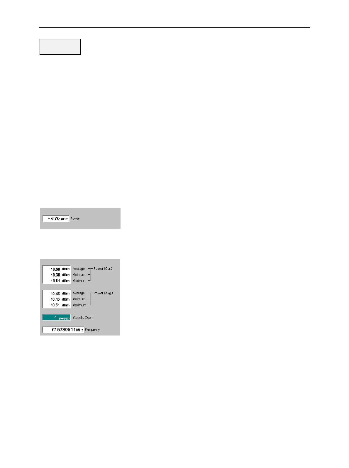
Pow. Meter Freq. Sel.:
The results for the frequency selective power meter (Pow. Meter Freq.
Sel.) application are displayed in several groups of output fields. All
results are obtained at the selected frequency and RBW. The statisti-
cal evaluation is based on a basic evaluation period/sweep of 4096
samples and on the statistics cycle (Statistic Count) defined in the
configuration menu (see section Analyzer/Generator Configuration on
p. 4.38 ff.; for a general description of statistical evaluations in the
CMU refer to Chapter 3, section General Settings).
Power (Curr.) Average, minimum and maximum power of the RF
input signal in the current sweep
Power (Avg.) Average, minimum and maximum of the Power
(Curr.) values: The Maximum (Minimum) value is
the largest (smallest) power ever measured in the
current measurement. Average is the average over
all Average – Power (Curr.) values in the current
measurement, obtained according to the averaging
rules described in Chapter 3, section General Set-
tings.
Statistic Count Number of sweeps per statistics cycle. The colored
bar indicates the relative measurement progress in
the statistics cycle
Frequency Frequency of the RF input signal. The frequency
can be measured with an accuracy of 0.1 Hz.

 Loading...


