CMU RF: Spectrum Measurement
1100.4903.12 4.53 E-10
Level
Scale
The Level Scale hotkey defines the total level range of the Spectrum test diagram
(ordinate scale). The ordinate scale is calculated from the Reference level (see
above) and the Level Scale such that
• The Reference level defines the upper edge of the diagram.
• The difference Reference level – Level Scale defines the lower edge of the
diagram.
• The number of horizontal grid lines (corresponding to 10, 15, or 16 cells) and
the ordinate labeling is adapted to the range.
Remote control
[SENSe:]POWer:LEVel:RANGe <Range>
Menus
The Menus softkey displays the hotkey bar for switching over to the other meas-
urement menus.
Measurement Results
The values represented in the measurement menu Spectrum can be divided into three groups:
Setting values
Scalar measurement results (marker values)
The trace plotted as a function of time
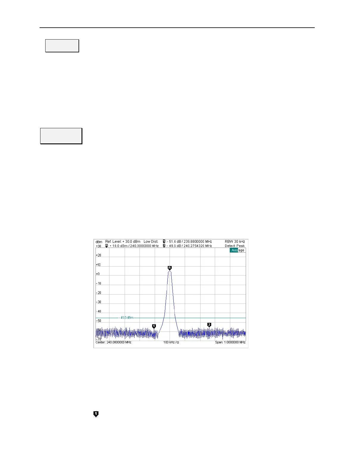
These values are indicated in two parameter lines and the test diagram:
Parameter line 1/2
Test diagram with
reference marker,
delta marker 1 and
2 and D-line.
Abscissa labels
Fig. 4-25 Display of measurement results (Spectrum menu)
Settings/
scalar measure-
ment results
Settings and scalar measurement results are indicated in the two parameter lines
above the test diagram
1
s
parameter line The first parameter line contains the following settings:
Ref. Level Reference level; upper edge of the diagram as set with the Ana-
lyzer Level – Ref. Level hotkey
Level and time of delta marker 1 (setting absolute) or difference
from reference marker (setting relative)
RBW Resolution bandwidth (Auto or numeric value)

 Loading...


