Hardware Interfaces CMU
1100.4903.12 8.16 E-8
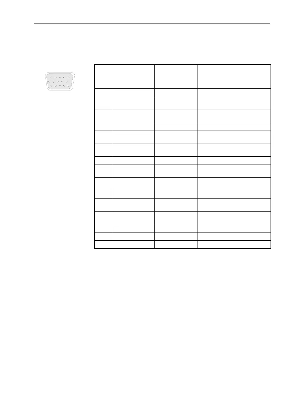
I/Q CH1 Connector (CMU200 with Option CMU-B17 only)
A 15-pin SUB-D female connector I/Q CH1 provides the inputs and outputs for I/Q signals (option CMU-
B17). The pin assignment is as follows:
I/ Q CH1
1
10
5
15
6
11
Fig. 8-17 I/Q CH1 connector
Pin Signal Input (I) /
Output (O) /
Bidirectional (B)
Description
1 GND – –
2 MOD_ I_ IN I I input, TX path,
max ±0.5 V, impedance 50 Ohm
3 MOD_Q_IN I Q input, TX path,
max ±0.5 V, impedance 50 Ohm
4 GND – –
5 MOD_I_OUT O I output, TX path,
max ±0.5 V, impedance 50 Ohm
6 MOD_Q_OUT O Q output, TX path,
max ±0.5 V, impedance 50 Ohm
7 GND – –
8 DEMOD_I_IN I I input, RX path,
max ±0.5 V, impedance 50 Ohm
9 DEMOD_Q_IN I Q input, RX path,
max ±0.5 V, impedance 50 Ohm
10 GND – –
11 DEMOD_I_OUT O I output, RX path,
max ±0.5 V, impedance 50 Ohm
12 DEMOD_Q_OUT O Q output, RX path,
max ±0.5 V, impedance 50 Ohm
13 GND – –
14 – – –
15 – – –

 Loading...


