CMU Connecting the CMU to the Test Setup
1100.4903.12 1.17 E-10
Connecting a Printer
LPT
A printer can be connected via the 25-contact parallel interface LPT at the
rear of the instrument (recommended) or one of the serial interfaces COM 1
or COM 2. For the interface description see section "Hardware Interfaces" in
chapter 8.
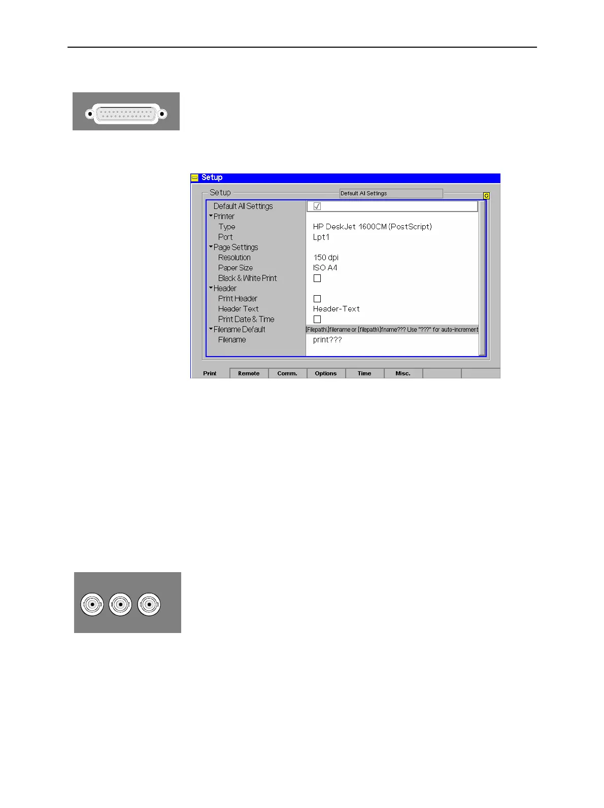
The printer type and port must be set in the Print tab of the Setup menu:
! To open the Setup – Print tab press the SETUP key at the front of the
instrument and activate the Print hotkey at the lower edge of the screen.
! In the Printer section set the printer type and port (COM 1 or COM 2 for
the serial (RS-232) ports; LPT 1 for the parallel printer port).
It is recommended to connect the output device to the parallel interface LPT,
if possible: With this selection, configuration of the interface is not
necessary; besides, the serial connectors may be used for GPIB bus etc.
Synchronization with External Devices; Connection of Further
Components
REF IN REF OUT 1 REF OUT 2
The three BNC female connectors REF IN, REF OUT 1, REF OUT 2 are
provided for synchronization of the CMU with external devices.

 Loading...


