CMU Hardware Interfaces
1100.4903.12 8.17 E-8
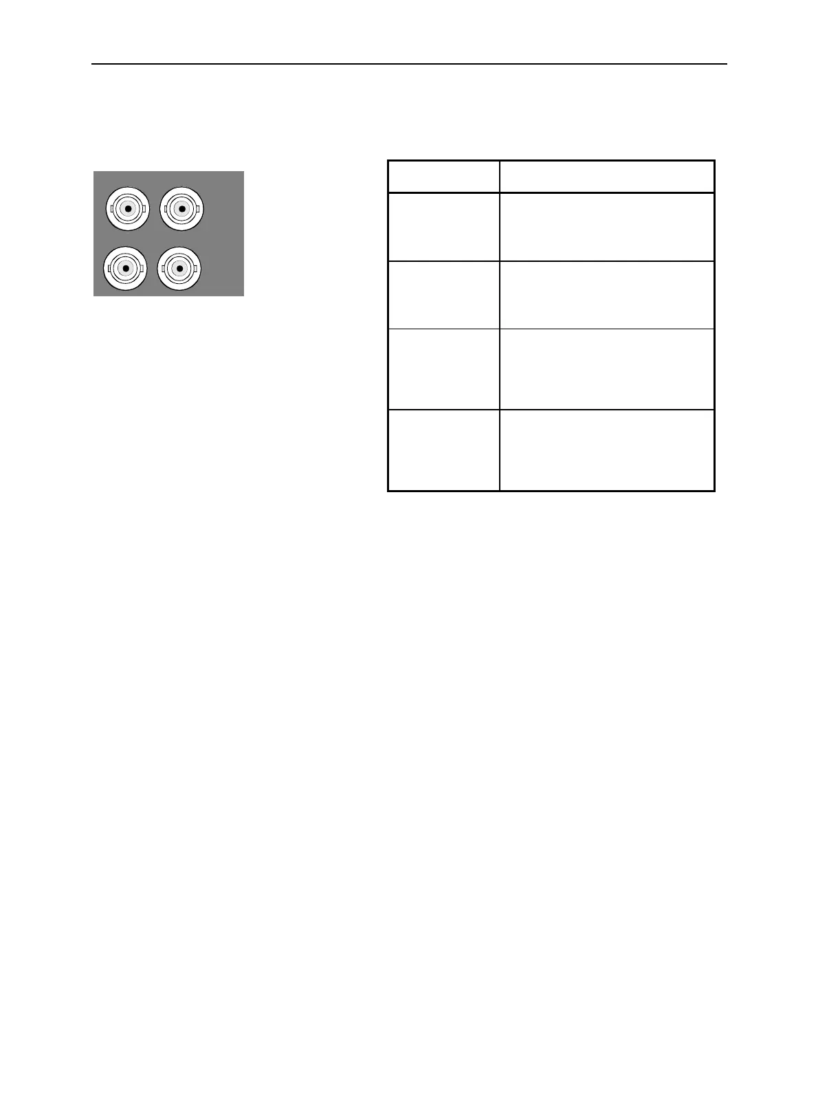
IF3 Connectors (CMU200 with Option CMU-B17 only)
Four BNC connectors provide the inputs and outputs for IF signals (option CMU-B17). The BNC shield
of all these connectors is connected to GND. The remaining specifications are as follows:
IF3 RX CH1 IN
IF3 RX CH1 OUT
IF3 TX CH1 IN
IF3 TX CH1 OUT
Fig. 8-18 IF3 connectors
Connector Function
IF3 RX CH1 IN IF input, RX path,
f= 7,68 MHz or 10,7 MHz;
max level +2 dBm PEP;
impedance 50 Ohm
IF3 RX CH1 OUT IF output, RX path,
f= 7,68 MHz or 10,7 MHz;
max level +4 dBm PEP;
impedance 50 Ohm
IF3 TX CH1 IN IF input, TX path,
f= 15,36 MHz or 13,85 MHz;
max level +3 dBm PEP for WCDMA,
max level –5 dBm for GSM;
impedance 50 Ohm
IF3 TX CH1 OUT IF output, TX path,
f= 15,36 MHz or 13,85 MHz;
max level +3 dBm PEP for WCDMA,
max level –5 dBm for GSM;
impedance 50 Ohm

 Loading...


