Front and Rear View CMU
1100.4903.12 1.6 E-10
0
12
3
45
6
78
9
.
-
ON / OFF ENTER
1100.0008.02
VARIATION
DATA
FUNCTION SYSTEM
CONTROL
DATA CTRL
MENU
SELECT
HELP
SETUP
mark
symb
E
F
B
M/µ
µV
W
C
dBµV
k/m
G/n
A
mV
D
1
dB
dBm
UNIT...
EXP/CMP CONT/HALT
RF4 IN
*
abc def
ghi
jkl mno
pqr
stu
vwx yz
_ µ
AF IN AF OUT
VOL
DEL
AUTO
INFO RESET
PRINT
*
#
Ω
AUX 1 AUX 2
SPEECH
AUX 3
DATA 2
13 dBm
MAX
2 W
MAX
50 W
MAX
13 dBm
MAX
RF 3 OUT
RF 2 RF 1
DATA 1
INS
CLR
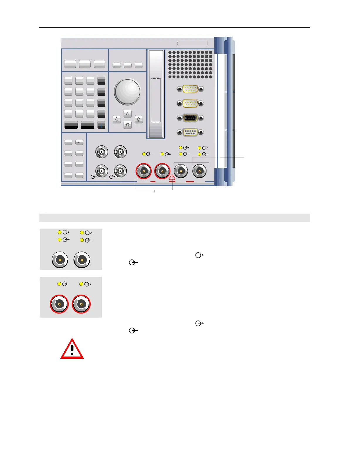
Bidirectional RF connectors
RF 1 und RF 2
Sensitive RF input, high-level RF output
Fig. 1-6 CMU front view– connectors
RF connectors
RF 2 RF 1
Bidirectional RF connectors for various power ranges
according to the data sheet.
The two LEDs above the connectors are illuminated as
long as the CMU sends signals
or is ready for re-
ception
.
!
Chapter 8,
"Hardware
connectors "
RF4 IN RF 3 OUT
Connector with high output level and connector for sen-
sitive RF measurements (antennas). Power ranges
according to the data sheet. Maximum permissible input
and output level according to the label on the front
panel.
The two LEDs above the connectors are illuminated as
long as the CMU sends signals
or is ready for re-
ception
.
Caution:
Note the maximum permissible input levels for all RF
connectors according to the label on the front panel or
the data sheet in order to prevent damage to the instru-
ment!
RF connectors may warm up very much when high RF
power is fed in!
!
Chapter 8,
"Hardware
connectors"

 Loading...


