CMU Hardware Interfaces
1100.4903.12 8.15 E-8
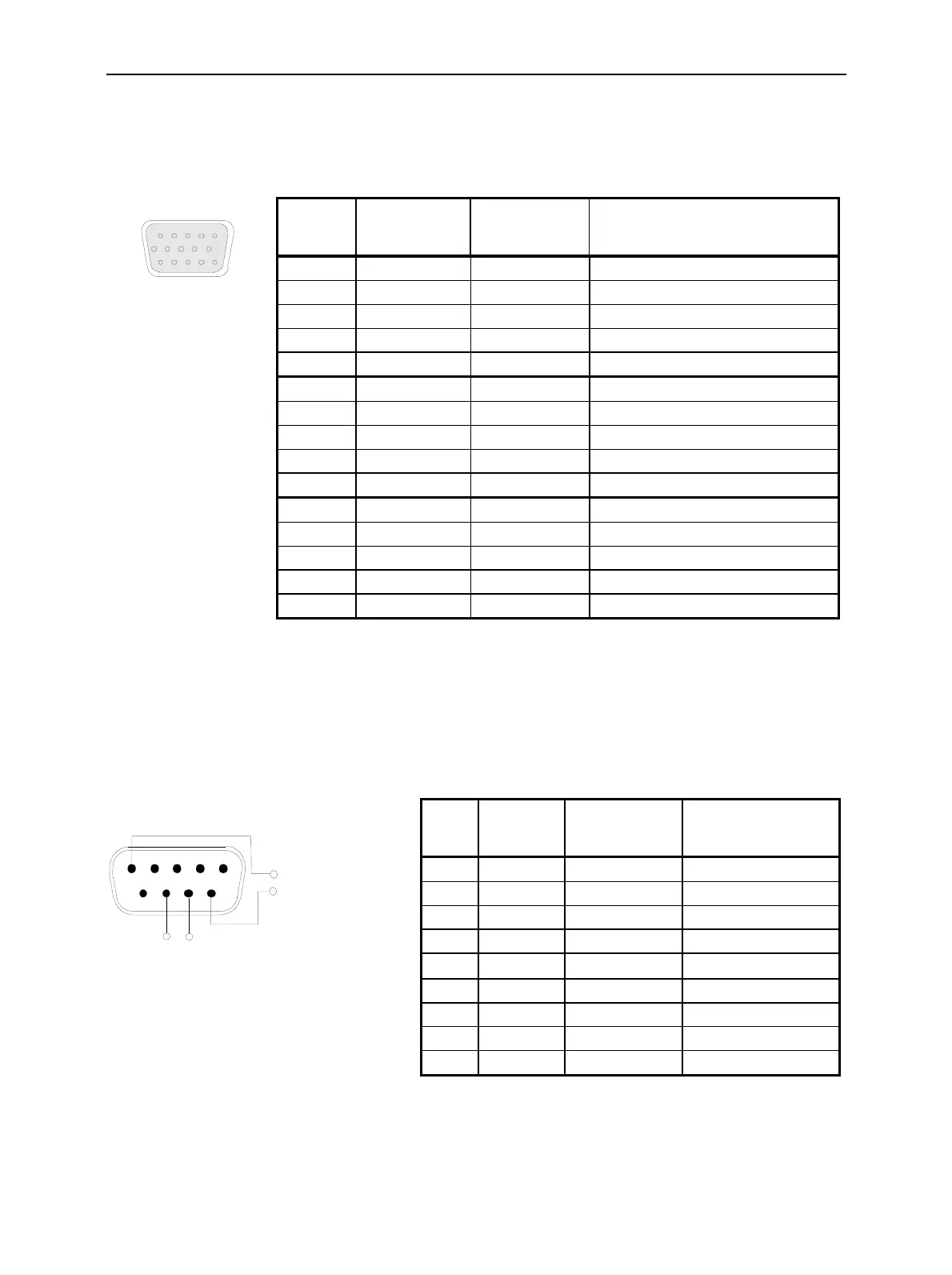
The 15-pin SUB-D female connector AUX 4 on the rear panel is used as an input or output for status,
control, and trigger signals. These signals are applied to definite pins of the AUX 4 connector (refer to
the corresponding menu).
The pin assignment of the AUX 4 connector is as follows:
AUX 4
1
10
5
15
6
11
Fig. 8-15 AUX 4 connector
Abis Connector (CMU300 with Option CMU-B71 only)
A 9-pin SUB-D female connector ABIS on the rear panel provides a symmetric (balanced) input of the
Abis Interface Unit for CMU (option CMU.B71; for CMU300 only). The pin assignment is as follows:
ABIS
12345
9
8
7
6
ABIS TX
(120
Ω
, symmetric)
ABIS RX
(120 Ω, symmetric)
Fig. 8-16 ABIS connector
1 GND B GND
2 GND B GND
3 GND B GND
4 GND B GND
5 GND B GND
6 GND B GND
7 GND B GND
8 GND B GND
9 TBUS8 B Status/control/trigger signal
10 TBUS9 B Status/control/trigger signal
11 TBUS10 B Status/control/trigger signal
12 TBUS11 B Status/control/trigger signal
13 TBUS12 B Status/control/trigger signal
14 TBUS13 B Status/control/trigger signal
15 TBUS14 B Status/control/trigger signal
Pin Signal Input (I) /
Output /
Bidirectional (B)
Description
Pin Signal Input (I) /
Output (O) /
Bidirectional (B)
Description
1 – – Not connected
2 – – Not connected
3 – – Not connected
4 – – Not connected
5 ABIS RX
I
Symmetric Abis input
6 ABIS RX I Symmetric Abis input
7 ABIS TX O For future extensions
8 ABIS TX O For future extensions
9 GND B GND

 Loading...


