Hardware Interfaces CMU
1100.4903.12 8.8 E-8
Handshake
Software handshake
In case of a software handshake data transfer is controlled using the two control characters XON /
XOFF:
• The CMU uses the control character XON to indicate that it is ready to receive data.
• If the receive buffer is full it sends the XOFF character via the interface to the controller. The
controller interrupts data output until it receives another XON from the CMU.
• In the same way the controller indicates to the CMU that it is ready to receive data.
1
2
3
4
5
6
7
8
9
DSUB connector, 9-pin / female
1
2
3
4
5
6
7
8
9
DCD
DSR
RxD
RTS
TxD
CTS
DTR
RI
GND
CMU Controller / PC
CMU Controller / PC
1
2
3
4
5
6
7
8
9
1
2
3
4
5
14
15
16
17
6
7
8
9
18
19
20
21
10
11
12
22
23
24
13
25
TxD
RxD
RTS
CTS
DSR
GND
DTR
DSUB connector, 9-pin / female
DSUB connector, 9-pin / female
DSUB connector, 25-pin / female
DCD
DSR
RxD
RTS
TxD
CTS
DTR
RI
GND
DCD
DSR
RxD
RTS
TxD
CTS
DTR
RI
GND
DCD
RI
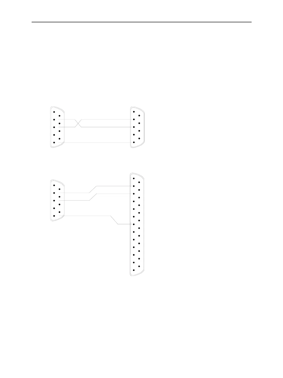
Connection between instrument
and controller (Null-modem cable)
The connection of the instrument to a
controller is made with a so-called
null-modem cable. Here, the data,
control and signalling lines must be
crossed. The wiring diagram on the
left applies to a controller with a 9-pin
or 25-pin configuration.
Fig. 8-3 Wiring of the data lines for software handshake

 Loading...


