Connecting the CMU to the Test Setup CMU
1100.4903.12 1.14 E-10
Connecting the CMU to the Test Setup
Warning:
Connect external devices and peripherals only when the instrument is
switched off or in STANDBY mode. Otherwise, future errors cannot be
excluded.
Connecting a Controller
The CMU can be connected to an external controller via the GPIB bus (IEEE bus according to standard
IEEE 488; throughout this documentation we will primarily use the term GPIB bus which is also used in
the operating menus and in the SCPI command syntax) or via serial interface:
Connection via GPIB
bus
IEEE 488
625
The CMU is connected to the GPIB interface of the controller via the GPIB
bus connector (IEEE 488 / IEC 625) at the rear of the instrument and a
shielded cable. The technical specifications of the GPIB interface are listed in
section "Hardware Interfaces " in Chapter 8.
GPIB Bus
Configuration
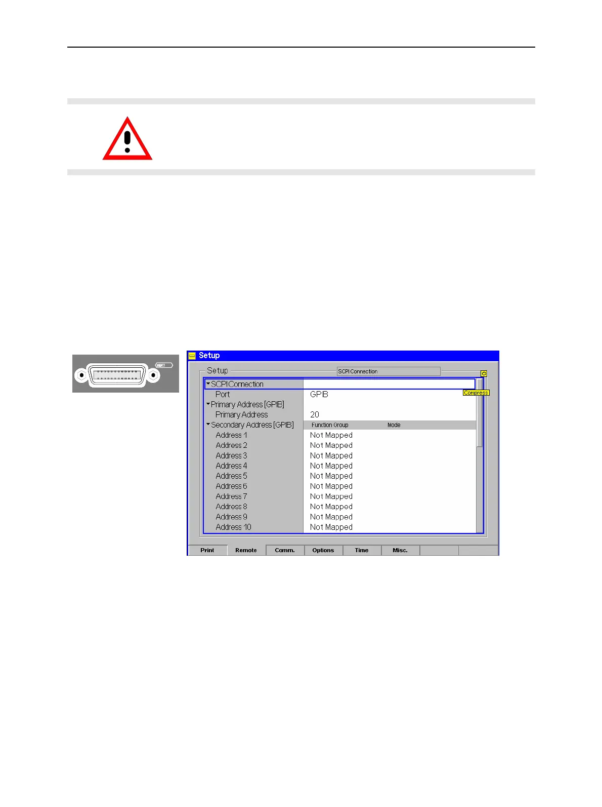
The parameters for GPIB bus control of the CMU are set in the Remote tab
of the Setup popup menu (in the following abbreviated by Setup – Remote,
see also chapter 4, Settings for Remote Control).
! To open the Setup - Remote menu, press the SETUP key at the front of
the instrument and activate the Remote hotkey at the lower edge of the
screen.
! Use the rotary knob to move the focus onto the SCPI Connection section
of the Setup table. If necessary, press the rotary knob or the ON/OFF
key to expand the parameters in the table (see Chapter 3).
! In the Port table row select the GPIB bus interface for transmission.
The bus address is factory-set to 20. It can be changed in the Primary
Address input field.

 Loading...


