Audio Generator and Analyzer (Option CMU-B41) CMU
1100.4903.12 4.90 E-10
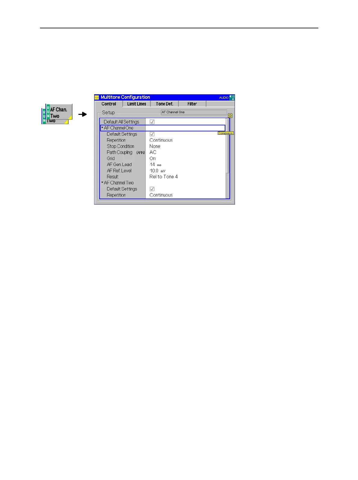
A settling time for the AF generator (AF Generator Lead)
The 0-dB line in the graphical diagram (AF Ref. Level)
Reference value for all levels in the graphical diagram (Result)
Besides, it configures the measurement diagram by adding or removing the Grid. All parameters can be
set independently for the two AF channels 1 and 2.
Fig. 4-41 Multitone Configuration – Control
Default Settings
The Default switch assigns default values to all settings in the Control tab (the de-
fault values are quoted in the command description in chapter 6 of this manual).
Two additional default switches reset all AF Channel One or all AF Channel Two
settings, respectively.
Remote Control
CONFigure:MULTitone:AFxChannel:CONTrol:REPetition
DEF, DEF, DEF (x = 1,2)
Repetition
Repetition determines the repetition mode, see chapter 3 and explanations given
on page 4.46 for the Power measurement. In Audio, one statistics cycle is termi-
nated when the system has settled and a valid result is available.
Remote control
CONFigure:MULTitone:AFxChannel:CONTrol:REPetition (x = 1,2)
CONTinuous | SINGleshot | 1 ... 10000,NONE,<Stepmode>
Stop Condition
Stop Condition defines a stop condition for the measurement:
None Continue measurement even if tolerance is exceeded
On Limit Failure Stop measurement if tolerance is exceeded
Remote control
CONFigure:MULTitone:AFxChannel:CONTrol:REPetition (x = 1,2)
CONTinuous | SINGleshot | 1 ... 10000,NONE,<Stepmode>
AF Path
Coupling
AF Path Couplingsets the input path for measurement of the AC or AC and DC
component of the AF signal:
AC DC component of the measured AF signal (including a possible
DC offset of the input amplifier) blocked. This ensures accurate

 Loading...


