Technical Specification R&S CMU-B17
1100.4903.12 TI.10 E-3
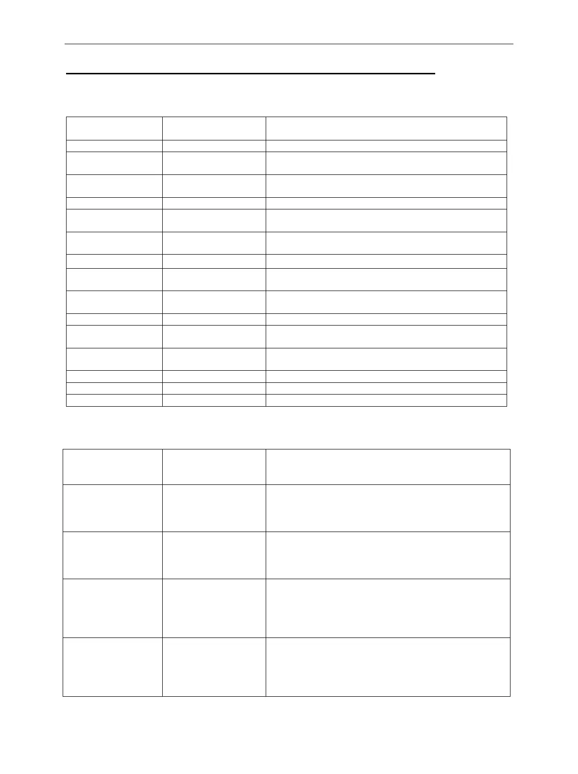
Annex 2: Assignment of IQ / IF connectors on R&S CMU rear panel
Sub-D connector I/Q CH1:
Pin Signal designation Function
1GND
2 MOD_ I_ IN I input, TX path,
max ±0.5 V, impedance 50 Ohm
3 MOD_Q_IN Q input, TX path,
max ±0.5 V, impedance 50 Ohm
4GND
5 MOD_I_OUT I output, TX path,
max ±0.5 V, impedance 50 Ohm
6 MOD_Q_OUT Q output, TX path,
max ±0.5 V, impedance 50 Ohm
7GND
8 DEMOD_I_IN I input, RX path,
max ±0.5 V, impedance 50 Ohm
9 DEMOD_Q_IN Q input, RX path,
max ±0.5 V, impedance 50 Ohm
10 GND
11 DEMOD_I_OUT I output, RX path,
max ±0.5 V, impedance 50 Ohm
12 DEMOD_Q_OUT Q output, RX path,
max ±0.5 V, impedance 50 Ohm
13 GND
14
15
BNC sockets:
Socket
designation
PIN* Function
IF3 RX CH1 IN BNC IF input, RX path,
f= 7,68 MHZ or 10,7 MHz;
max level +2 dBm PEP;
impedance 50 Ohm
IF3 RX CH1 OUT BNC IF output, RX path,
f= 7,68 MHZ or 10,7 MHz;
max level +4 dBm PEP;
impedance 50 Ohm
IF3 TX CH1 IN BNC IF input, TX path,
f= 15,36 MHz or 13,85 MHz;
max level +3 dBm PEP for WCDMA,
max level –5 dBm for GSM;
impedance 50 Ohm
IF3 TX CH1 OUT BNC IF output, TX path,
f= 15,36 MHz or 13,85 MHz;
max level +3 dBm PEP for WCDMA,
max level –5 dBm for GSM;
impedance 50 Ohm
*) The BNC shield is GND.

 Loading...


