RF Non Signalling Measurements CMU
1100.4903.12 2.8 E-9
RF Non Signalling Measurements
In the RF Non Signalling mode, a continuous or pulsed RF signal can be generated and a RF signal
with definite frequency characteristics can be analyzed. The signal level can be plotted in oscillographi-
cal (Power) or spectral (Spectrum) representation.
MENU
SELECT
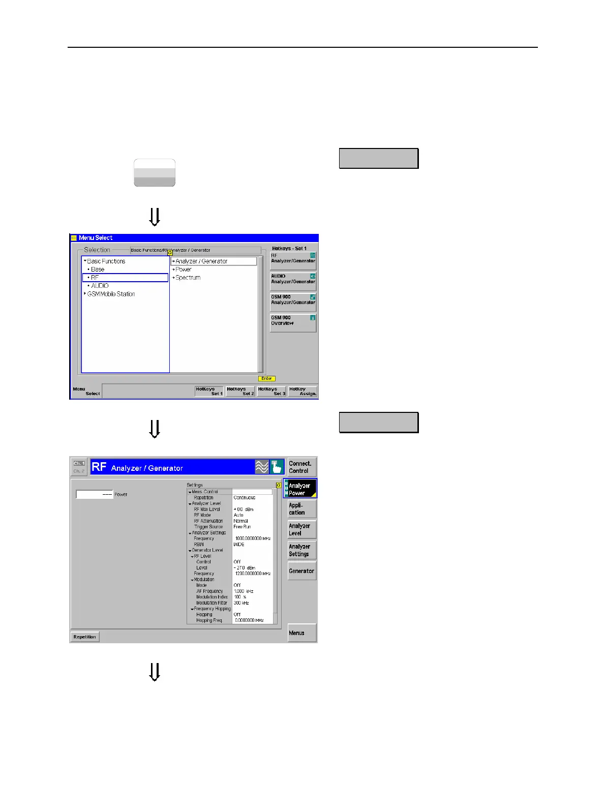
Step 1
! Press the Menu Select key to open the
Menu Select menu.
"
! Use the cursor keys and the rotary knob
to select the RF function group in the
left half of the Selection table.
! In the right half of the table, select the
Analyzer/Generator menu.
! Press the Enter key to activate the
measurement selected and open the
RF Analyzer/Generator menu.
Step 2
In the Settings table the Ana-
lyzer/Generator menu indicates the pa-
rameters of the signal generated and those
of the signal received and analyzed.
#
At present, all parameters have been reset
to factory default values. Different soft-
key/hotkey combinations and popup
menus are provided to change the set-
tings. User-defined parameters will be
saved for later sessions when the CMU is
switched off.
The Power output field in the Ana-
lyzer/Generator menu shows an invalid
result ("---") because at present no RF
input signal is applied to the CMU.

 Loading...


