RM0401 Rev 3 127/771
RM0401 Reset and clock control (RCC)
134
5.3.14 RCC Backup domain control register (RCC_BDCR)
Address offset: 0x70
Reset value: 0x0000 0000, reset by Backup domain reset.
Access: 0 ≤ wait state ≤ 3, word, half-word and byte access
Wait states are inserted in case of successive accesses to this register.
The LSEON, LSEBYP, RTCSEL and RTCEN bits in the Section 5.3.14: RCC Backup
domain control register (RCC_BDCR) are in the Backup domain. As a result, after Reset,
these bits are write-protected and the DBP bit in the Section 4.4.1: PWR power control
register (PWR_CR) has to be set before these can be modified. Refer to Section 5.1.2:
Power reset for further information. These bits are only reset after a Backup domain Reset
(see Section 5.1.3: Backup domain reset). Any internal or external Reset will not have any
effect on these bits.
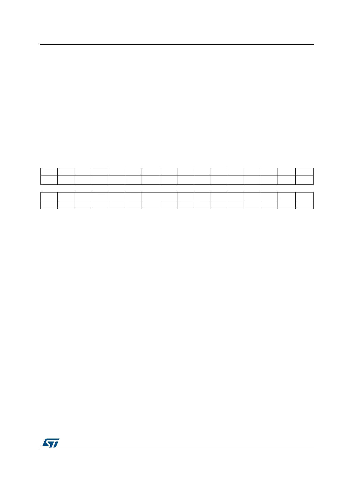
31 30 29 28 27 26 25 24 23 22 21 20 19 18 17 16
Res. Res. Res. Res. Res. Res. Res. Res. Res. Res. Res. Res. Res. Res. Res. BDRST
rw
15 14 13 12 11 10 9 8 7 6 5 4 3 2 1 0
RTCEN Res. Res. Res. Res. Res. RTCSEL[1:0] Res. Res. Res. Res.
LSEMO
D
LSEBYP LSERDY LSEON
rw rw rw rw r rw
Bits 31:17 Reserved, must be kept at reset value.
Bit 16 BDRST: Backup domain software reset
Set and cleared by software.
0: Reset not activated
1: Resets the entire Backup domain
Bit 15 RTCEN: RTC clock enable
Set and cleared by software.
0: RTC clock disabled
1: RTC clock enabled
Bits 14:10 Reserved, must be kept at reset value.
Bits 9:8 RTCSEL[1:0]: RTC clock source selection
Set by software to select the clock source for the RTC. Once the RTC clock source has been
selected, it cannot be changed anymore unless the Backup domain is reset. The BDRST bit
can be used to reset them.
00: No clock
01: LSE oscillator clock used as the RTC clock
10: LSI oscillator clock used as the RTC clock
11: HSE oscillator clock divided by a programmable prescaler (selection through the
RTCPRE[4:0] bits in the RCC clock configuration register (RCC_CFGR)) used as the RTC
clock
Bits 7:4 Reserved, must be kept at reset value.
Bit 3 LSEMOD: External low-speed oscillator bypass
Set and reset by software to select crystal mode for low speed oscillator. Two power modes
are available.
0: LSE oscillator “low power” mode selection
1: LSE oscillator “high drive” mode selection